Melt spinning device

A melt-spinning and guiding device technology, which is applied in transportation and packaging, textiles and papermaking, and thin material processing, and can solve problems such as the impossibility of stable positioning and directional guidance of yarns

Active Publication Date: 2022-04-26
OERLIKON TEXTILE GMBH & CO KG
View PDF18 Cites 0 Cited by
  • Summary
  • Abstract
  • Description
  • Claims
  • Application Information

AI Technical Summary

Problems solved by technology

However, in the case of relatively large height differences, undesired elastic properties occur in the guidance of the automatic handling unit, which make it impossible to stabilize the yarn in position and thus to guide it directional

Method used


Image

  • Melt spinning device
  • Melt spinning device
  • Melt spinning device

Examples


Embodiment Construction

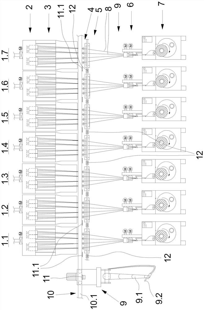
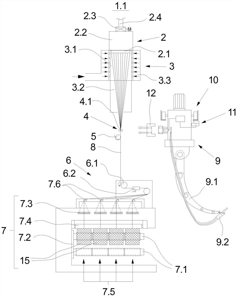
[0024] An embodiment of the melt-spinning device of the invention with a plurality of spinning positions is in figure 1 and image 3 The front view and side view are shown. The following descriptions apply to both figures unless one of them is explicitly mentioned.

[0025] An embodiment of the melt-spinning device according to the invention has a plurality of spinning positions 1.1-1.7, which are arranged next to each other in a row and form machine longitudinal sides. like figure 1 The number of spinning positions shown is exemplary only. In principle, such a melt spinning unit contains several spinning positions of the same type.

[0026] like figure 1 and image 3 The spinning positions 1.1-1.7 shown are designed identically in terms of their structure. The following will be as image 3 The spinning position 1.1 shown in the side view is taken as an example to describe these devices in more detail.

[0027] Each spinning position 1.1-1.7 has a spinning nozzle arra...


PUM


Abstract

The invention relates to a melt-spinning device for the manufacture of synthetic yarns, having a plurality of spinning positions. Each spinning position has a spinning nozzle unit, a cooling unit, a guide disc unit and a winding unit. An automatic handling unit is provided for joining the yarn at the spinning positions, which can be guided to each spinning position for joining the yarn. In order to obtain a reliable guidance and precise positioning for engaging the yarn, according to the invention, the guiding device is formed by a suspended track on which the automatic operating unit is guided, wherein the automatic operating unit is in a positionally fixed manner in the spinning position It is held in the suspended track by a controllable locking mechanism.

Description

technical field [0001] The present invention relates to a melt-spinning device for the manufacture of synthetic yarns. Background technique [0002] Synthetic yarn production is carried out with such a melt-spinning device with several spinning positions. Here, the spinning positions are arranged next to each other to form a machine longitudinal front. Each spinning position has a spinning nozzle arrangement with several spinning nozzles for extruding a number of yarns. The yarns of the spinning positions are withdrawn together as yarn groups from the spinning nozzles and wound up in parallel at the end of the process to form winding bobbins at a number of winding points of the winding device. The winding devices in the spinning position are each equipped with two winding spindles, which are held on their winding turret, so that the yarn can be produced continuously in the spinning position. Only at the start of the production process or in the event of an interruption of...

Claims


Application Information

Patent Timeline
Patent Type & Authority Patents(China)
IPC IPC(8): D01D13/02B65H57/28
CPCB65H57/28D01D13/02B65H2701/3132
Inventor M-A·赫尔恩多夫R·沃斯S·福尔斯蒂奇
Owner OERLIKON TEXTILE GMBH & CO KG
Why Eureka
Try Eureka