Assembling and disassembling process of umbrella ribs and upper nest

An umbrella rib and process technology, applied in the field of umbrellas, can solve problems such as user inconvenience, difficult operation, scratched fingers, etc., and achieve the effect of overcoming low efficiency, high tensile strength, and low artificial influence.

Active Publication Date: 2019-11-19
晋江集成轻工有限公司
View PDF4 Cites 0 Cited by
  • Summary
  • Abstract
  • Description
  • Claims
  • Application Information

AI Technical Summary

Problems solved by technology

[0004] The above-mentioned structure has the following disadvantages: the upper rib and the lower rib are hinged in the upper rib nest and the lower rib nest, and they must be connected in series with iron wires and then inserted into the hinges of the upper rib nest and the lower rib nest respectively. In the knot groove, the iron wire connecting the upper and lower umbrella ribs in series will produce a sharp winding part after winding. If the user does not pay attention, it will scratch the fingers, and the tightness of the iron wire depends on manual control, or loose or Tightness is not good for the up and down flipping and use of the umbrella ribs. In addition, because all the umbrella ribs are connected in series on the wire, it is impossible to disassemble a single umbrella rib and all need to be opened, which is inconvenient for the user and difficult to operate.

Method used


Image

  • Assembling and disassembling process of umbrella ribs and upper nest
  • Assembling and disassembling process of umbrella ribs and upper nest
  • Assembling and disassembling process of umbrella ribs and upper nest

Examples


Embodiment Construction

[0038] The present invention will be further described below in conjunction with accompanying drawing:

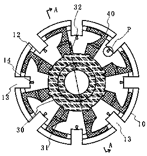
[0039] Such as Figure 3-11 As shown, this embodiment provides an improved upper nest structure for an umbrella, including a nest base 10 and a nest cover 20 .

[0040] In this embodiment, the center of the top of the nest 10 is provided with a seat hole 11 penetrating up and down and an operating circular member 30 concentrically arranged on the periphery of the seat hole 11, and the top edge of the nest 10 is provided with a cross-section circular ring. The chute 12 is arranged concentrically with the seat hole 11 and a plurality of accommodating grooves 13 arranged at equal circumferential intervals and communicated with the chute 12 .

[0041] Between the operating round member 30 and the chute 12, there are sliding pieces 40 that match the number of the accommodating grooves 13 at equidistant circumferential intervals. Each sliding piece 40 has strong rigidity and is ...


PUM


Abstract

The invention relates to an assembling and disassembling process of umbrella ribs and an upper nest. The process comprises the integral hanging process for completing the hanging of all the umbrella ribs once and the individual umbrella rib detaching and replacing process for independently detaching the umbrella ribs from the upper nest and then carrying out assembling. The detaching and replacingprocess specifically comprises the following steps that a baffle nail on a clamping hole is removed, through plane rotation and upward lifting of an operation round part carried out sequentially, andunder the upward pulling state, plane rotation is carried out so that a target sliding plate and a target umbrella rib are separated; and during single umbrella rib mounting, through plane rotation and upward lifting of the operation round part carried out sequentially, under the upward pulling state, plane rotation is carried out, so that the outer end of the target sliding plate penetrates intoa pivoting hole of a new umbrella rib, finally, plane rotation is carried out till reaching the intimal position after loosing operation, and the baffle nail is used for realizing re-locking. The integral hanging process comprises the followings steps: under the assistances of a tool, the plane of the operation round part flatwise rotates to a specified angle under the downward pressing state, and then the outer ends of sliding plates penetrate through pivoting holes at the inner ends of the umbrella ribs. All the umbrella ribs can be assembled in place once, independent assembling and disassembling also can be carried out, the structure is stable, and the user operation and use are facilitated.

Description

technical field [0001] The invention relates to the technical field of umbrellas, in particular to a process for disassembling and assembling umbrella ribs and upper nests. Background technique [0002] The rib nest structure in the prior art includes: a main rib, an upper rib nest, a retaining tube, a lower rib nest, eight upper ribs, eight lower ribs and two iron wires, wherein the upper rib nest is a A short cylinder with a through hole in the center, a pin hole in the middle of the outer edge, eight pivot grooves at equal angles on the outer edge, a storage groove in the middle, and a long cylinder with a through hole in the center. , the upper end is a large honeycomb part, and its outer edge is equipped with eight pivotal grooves at equal angles, and there is a receiving groove in the middle. The end of the upper rib is flat, with a pivot hole on it, and the end of the lower rib The part is flat, and a pivot hole is opened on it. [0003] When assembling, first fix t...

Claims


Application Information

Patent Timeline
Patent Type & Authority Applications(China)
IPC IPC(8): A45B25/02A45B25/06
CPCA45B25/02A45B25/06Y02A40/81
Inventor 林贞双李志民张向峰
Owner 晋江集成轻工有限公司
Why Eureka
Try Eureka