Clip device used in coordination with endoscope and clipping part of clip device

An endoscope and a clamping part technology, applied in the field of a clamp device and its clamping part, can solve the problems of inconvenient and reliable surgical operation, unreliable movement positioning, complex assembly structure, etc., and achieve stable structure, firm clamping, High stability effect

Pending Publication Date: 2019-11-19
ANREI MEDICAL HZ
View PDF5 Cites 12 Cited by
  • Summary
  • Abstract
  • Description
  • Claims
  • Application Information

AI Technical Summary

Problems solved by technology

However, the inventor believes that in this structure, there are many parts, the assembly structure is complicated, and the process steps are many, and the movable positioning between the clip and the clip holder is not reliable enough, and the operation is not convenient and reliable enough, and further improvement is still needed. reduce manufacturing costs

Method used


Image

  • Clip device used in coordination with endoscope and clipping part of clip device
  • Clip device used in coordination with endoscope and clipping part of clip device
  • Clip device used in coordination with endoscope and clipping part of clip device

Examples


Embodiment 1

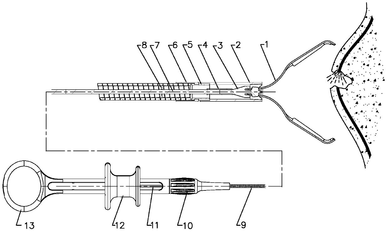
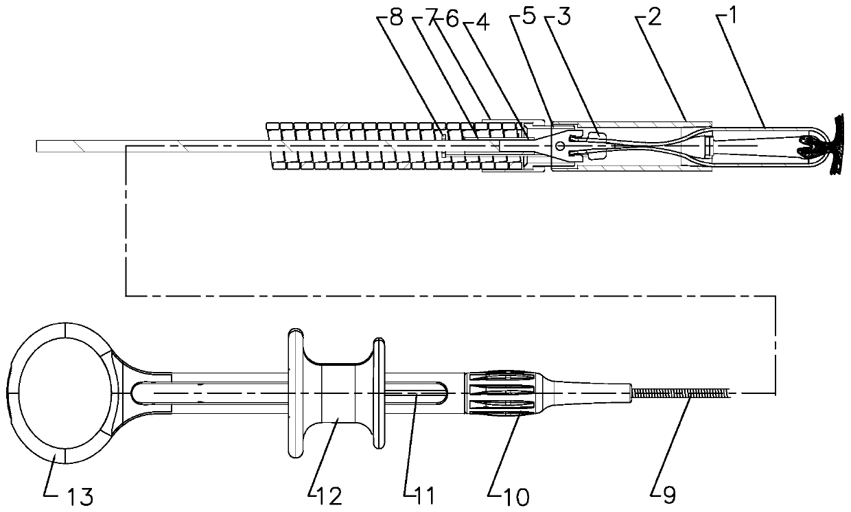
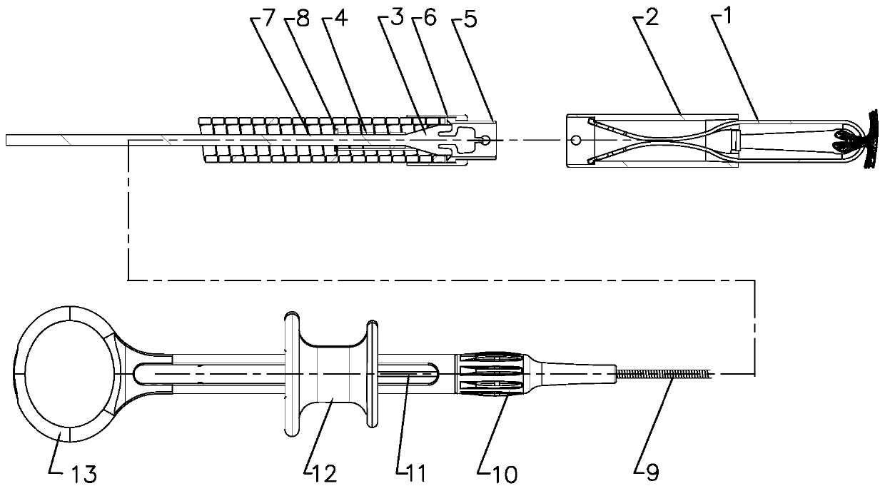
[0050] Such as Figures 1 to 3 The shown clip device for use with an endoscope includes an operating part, a releasing part and a clamping part. For the structural operation of the operating part and the releasing part, reference may be made to the patent document with publication number CN108013914A. The specific instructions are as follows:

[0051] The distal end of the mandrel 7 in the operation part is fixedly connected with the connecting pipe 4 in the clamping part, the spring hose 9 in the release part is sleeved on the mandrel 7, and the proximal end of the spring hose 9 is connected to the operation part, The far end of the spring hose 9 fixes the swivel seat 6 in the release part, the swivel seat 6 is equipped with a swivel 5, and the swivel 5 is detachably connected with the clamp tube 2 in the clamping part; the operating part pulls The mandrel 7 drives the clip fixing seat 3 to move back to clamp the clip 1, the shoulder of the clip 1 is limited by the clamp tu...

Embodiment 2

[0063] A clip device used with an endoscope, comprising an operating part, a releasing part and a clamping part. The difference from Example 1 is only the following structure of the clamping part:

[0064] Such as Figure 13 , Figure 14 , Figure 15 As shown, the outer end of the radial pin portion 310 extends backward to form the protection wing portion 320 , and a third gap 323 is formed between the protection wing portion 320 and the front end surface of the clip holder 3 . In this way, forming the protective wings on the radial pins can further shorten the length of the tail of the clip, thereby shortening the length of the clip and the clamp tube and the length of the clip indwelling the patient. Others are the same as in Example 1.


PUM


Abstract

The invention relates to a clip device used in coordination with an endoscope, and the clipping part of the clip device comprises clips, a clip tube, a clip fixing base and a connecting tube. The chipfixing base is positioned in the clip tube and can move forward and backward, the connecting tube is fixed at the back end of the clip fixing base, the tail parts of the two clips are stored in the clip tube and are movably connected with the front end of the clip fixing base through a deformation hole, and the inner wall of the tail part of the clip tube is provided with a stop step. When the two clips are clamped, the protruding parts at the tail parts of the clips are blocked on the stop step, the front end of the clip fixing base extends forward to form a connecting part, the front part of the connecting part protrudes to the left and right sides respectively to form radial pin parts, and the tail parts of the two clips are respectively sleeved on the two radial pin parts through thedeformation hole to realize the movable connection between the clips and the clip fixing base. According to the present invention, the scheme has reliable structure, convenient release, fewer components and parts, easier manufacturing and lower cost.

Description

technical field [0001] The invention relates to a clip device and its clamping part used in conjunction with an endoscope, specifically, it is used for suturing surgical wounds under the endoscope to stop bleeding or prevent delayed bleeding, or for temporarily clamping tissues to fix other equipment, or for purposes such as position marking. Background technique [0002] With the development of endoscopic technology and other related technologies, endoscopic hemostasis has become the first choice for the treatment of gastrointestinal bleeding. Currently commonly used endoscopic hemostasis methods include laser coagulation, electrocoagulation, local injection of drugs to stop bleeding, drug spraying, and hemostatic clip clamping. Among them, hemostatic clip clipping method has become the most effective non-surgical treatment of gastrointestinal bleeding due to its characteristics of small trauma, fast hemostasis, low incidence of rebleeding, few complications, and definite ...

Claims


Application Information

Patent Timeline
Patent Type & Authority Applications(China)
IPC IPC(8): A61B17/122A61B17/128A61B17/00
CPCA61B17/122A61B17/1222A61B17/1285A61B17/00234A61B2017/12004A61B17/1227A61B1/00087
Inventor 胡晓刚
Owner ANREI MEDICAL HZ
Why Eureka
Try Eureka