Interbody fusion cage

An intervertebral fusion device and fusion device technology, which is applied in the field of intervertebral fusion devices, can solve the problems of inconvenient implantation of intervertebral fusion devices, damage to vertebral endplates, cumbersome operations, etc., so as to shorten operation time and reduce the risk of injury The effect of reduction and easy operation

Active Publication Date: 2019-11-19
BEIJING JISHUITAN HOSPITAL
View PDF14 Cites 3 Cited by
  • Summary
  • Abstract
  • Description
  • Claims
  • Application Information

AI Technical Summary

Problems solved by technology

And if the effect of deformity correction is to be achieved, the thickness of the first side of the intervertebral cage must be greater than the current height of the intervertebral space, so that when the intervertebral cage is implanted, it will be in contact with the upper vertebral body and the lower vertebral body. Interference, which can easily lead to damage to the vertebral endplate
[0004] There is another kind of intervertebral fusion device for kyphoscoliosis, although it can reduce the damage to the vertebral body endplate to a certain extent, but this kind of intervertebral fusion device is not only complicated in structure and cumbersome to operate, but also because it can only be used from the lumbar spine. Implanted through the posterior approach, so it is neither suitable for interbody fusion surgery through the anterior approach of the lumbar spine, nor is it convenient to implant a larger volume intervertebral fusion device

Method used


Image

  • Interbody fusion cage
  • Interbody fusion cage
  • Interbody fusion cage

Examples


Embodiment Construction

[0032] In the following detailed description of specific embodiments, reference is made to the accompanying drawings which form a part hereof. The accompanying drawings show, by way of example, specific embodiments in which the invention can be practiced. The exemplary embodiments are not intended to be exhaustive of all embodiments in accordance with the invention. It is to be understood that other embodiments may be utilized, and structural or logical changes may be made, without departing from the spirit and scope of the present invention. Accordingly, the following detailed description is not limiting, and the scope of the invention is defined by the appended claims.

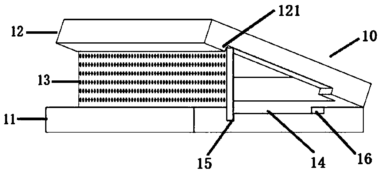
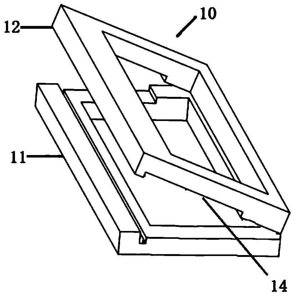
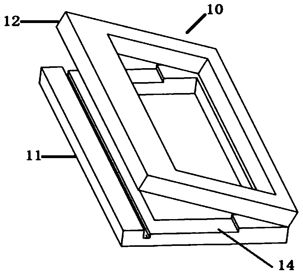
[0033] figure 1 It is a schematic diagram of the overall structure of the intervertebral fusion device according to an embodiment of the present invention. Such as figure 1 As shown, in one embodiment of the present invention, a kind of intervertebral fusion device is provided, which is suitable for the ...


PUM


Abstract

The invention relates to an interbody fusion cage, which includes an interbody fusion cage main body and a lamellar propping-open part. The interbody fusion cage main body includes an upper supportingpart and a lower supporting part which are mutually hinged, an accommodating groove is formed in the lower surface of the upper supporting part and/or the upper surface of the lower supporting part to be used for accommodating the lamellar propping-open part in a horizontal state, a supporting groove is formed in the upper surface of the lower supporting part to be used for clamping the lamellarpropping-open part in a vertical state, the accommodating groove includes an opening extending to the side edge of the upper supporting part and/or the lower supporting part to enable the lamellar propping-open part to rotate from the horizontal state to the vertical state through the opening, and thus the interbody fusion cage main body is propped open. According to the interbody fusion cage, damage to a human body can be greatly reduced during operation, the structure is also simple, operation is convenient, and the interbody fusion cage can be applied to interbody fusion surgery of lumbar vertebra lateral anterior approach.

Description

technical field [0001] The invention relates to the technical field of medical instruments, and more specifically, to an intervertebral fusion device. Background technique [0002] Lumbar lateral anterior approach interbody fusion (Oblique Lumber Interbody Fusion, referred to as OLIF) is a relatively new spinal surgery method, the approach of this operation is less traumatic, and a larger interbody fusion device can be implanted, which helps It can better restore the intervertebral space height, lordosis and coronal plane balance, and can also indirectly decompress, thereby reducing nerve damage and adhesion. For patients with kyphoscoliosis, the gap between the two vertebral bodies is smaller on the side near the front of the body and larger on the side near the back of the body. If an intervertebral fusion cage of equal thickness is implanted, Then the effect of correcting the spine cannot be achieved. [0003] There is an intervertebral fusion cage for kyphoscoliosis. T...

Claims


Application Information

Patent Timeline
Patent Type & Authority Applications(China)
IPC IPC(8): A61F2/44A61F2/30
CPCA61F2/30771A61F2/447A61F2002/3006A61F2002/30329A61F2002/30518A61F2002/30784A61F2002/3093
Inventor 韩骁行勇刚田伟
Owner BEIJING JISHUITAN HOSPITAL
Why Eureka
Try Eureka