Supercharge Your Innovation With Domain-Expert AI Agents!

Wireless Smart Mat

A wireless and wireless transmission technology, applied in special positions of vehicles, pulse technology, electronic switches, etc., can solve the problems of installation complexity, induction inaccuracy, complicated installation and difficult safety, etc., to improve safety and increase installation convenience. sexual effect

Active Publication Date: 2021-11-23
ZEALIO ELECTRONICS
View PDF0 Cites 0 Cited by
  • Summary
  • Abstract
  • Description
  • Claims
  • Application Information

AI Technical Summary

Problems solved by technology

[0004] In terms of the structure controlled by the magnetic buckle switch, since the magnet is set in the door, the pedal is in the lower part where the vehicle door can be seen, and the two are switched by magnetic induction. Although it saves power, the magnet is not easy to install on the Move relative to the position of the induction switch, which will lead to the situation of inaccurate induction
[0005] In terms of the structure controlled by infrared switches or ultrasonic switches, since the vehicle electric power must be used for power supply, it is necessary to have a wire pulling connection product inside the vehicle, which causes complicated installation and safety issues.
[0006] Therefore, whether it is a car floor mat with a luminous function or a welcome panel on the market, the installation method must be electrically connected to the vehicle power supply through a wire, which will easily cause installation complexity and safety concerns. There are many missing problems such as doubts, and it will cause the overall volume of the floor mat and welcome trim to be unable to be thinned

Method used


Image

  • Wireless Smart Mat
  • Wireless Smart Mat
  • Wireless Smart Mat

Examples


Embodiment Construction

[0068] The present invention will be further elaborated below in conjunction with accompanying drawing and specific embodiment;

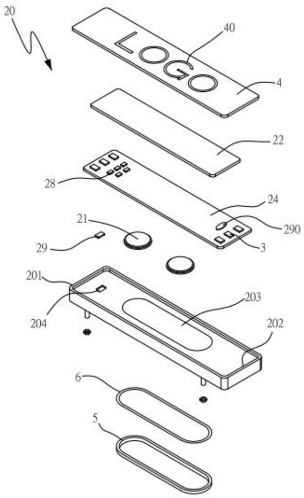
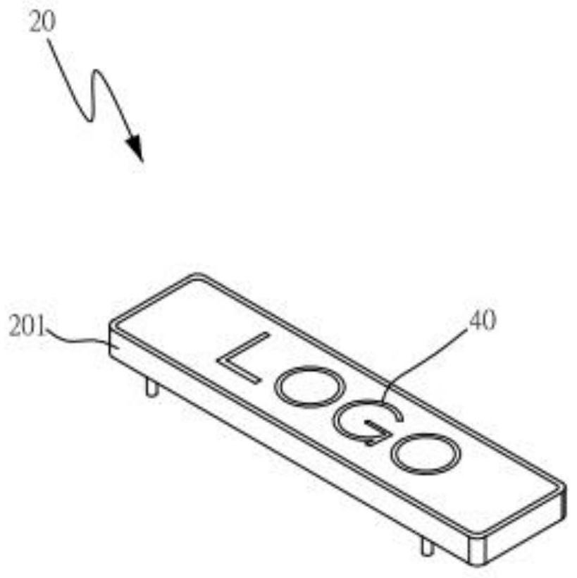
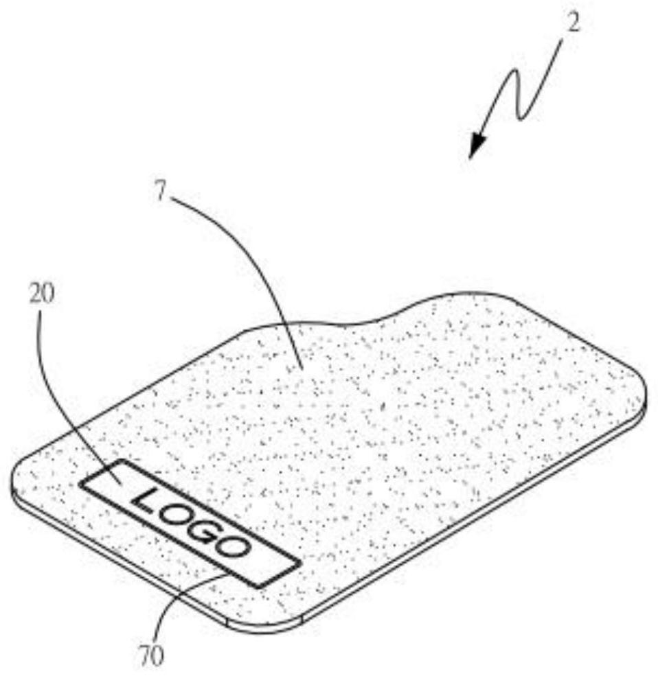
[0069] see figure 1 , figure 2 and image 3 , are respectively the three-dimensional exploded view, the three-dimensional combination view and the three-dimensional view of the first embodiment of the wireless smart mat of the present invention. As shown in the figure, a wireless smart mat 2 can receive a signal detected by a transmitting terminal It should be noted that the sending end 8 can be installed in a welcome panel, on a relevant position of a car door 90 or on a door frame 91 of a car body 9 (please also refer to Figure 12 ), the wireless smart mat 2 includes a display mat unit 20 and a foot mat 7, and it should be noted that the foot mat 7 is correspondingly installed in the bottom of the car body 9.

[0070] Continued please refer to Figure 4 and Figure 5 The display mat unit 20 includes a frame body 201, a backlight module 22, ...


PUM


Abstract

A wireless smart mat, comprising a display mat unit and a foot mat, the display mat unit includes a frame, a backlight module, at least one magnetic sensing module, a first wireless transmission receiving module, a gravity Sensing module, a first control module, a panel and a bottom plate, one side of the frame body has a groove to form an accommodating part to accommodate a power supply module and a magnetic element, the backlight module is accommodated in the groove and It includes at least one circuit board electrically connected to the power supply module, a plurality of light-emitting components are arranged on the circuit board, the first wireless transmission receiving module is arranged on the circuit board to receive the induction signal, and the gravity sensing module is arranged on the The circuit board is used to detect an acceleration change and generate a voltage signal. The first control module is arranged on the circuit board and turns on and off the backlight module according to the sensing signal and the voltage signal. The bottom board is assembled on the frame On the other side, the display mat unit is installed in the foot mat.

Description

technical field [0001] The invention relates to a wireless intelligent stepping mat, in particular to a wireless intelligent stepping mat that can greatly improve safety, facilitate installation, achieve thinning and have energy-saving effects. Background technique [0002] At present, the car floor mat technology with luminous function on the market usually needs to be electrically connected to the power supply of the car. Its installation is very complicated and difficult and has safety problems, or its design is heavy and large, and it cannot be compatible with any Style foot pads. [0003] In addition, generally, the existing welcome panels on the market use a magnetic switch, an infrared switch or an ultrasonic switch to control the opening and closing of the lamp body (such as a lighting lamp or a light-emitting diode, etc.). [0004] In terms of the structure controlled by the magnetic buckle switch, since the magnet is set in the door, the pedal is in the lower part...

Claims


Application Information

Patent Timeline
Patent Type & Authority Patents(China)
IPC IPC(8): B60N3/04B60Q3/217H03K17/95H03K17/955
CPCB60N3/048B60Q3/217H03K17/9517H03K17/955
Inventor 郑家保郭宝麟邓安村
Owner ZEALIO ELECTRONICS
Features
  • R&D
  • Intellectual Property
  • Life Sciences
  • Materials
  • Tech Scout
  • Unparalleled Data Quality
  • Higher Quality Content
  • 60% Fewer Hallucinations
Learn More