
Installation structure for drainage pipeline and installation process thereof

A technology for installing structures and drainage pipes, which is applied in the sewer system, waterway system, water supply device, etc., can solve the problem of easy damage of the pipe body, and achieve the effect of improving the convenience of construction and improving the anti-settling ability.

Active Publication Date: 2019-11-19
广州凌鼎建筑工程有限公司
View PDF9 Cites 4 Cited by
  • Summary
  • Abstract
  • Description
  • Claims
  • Application Information

AI Technical Summary

Problems solved by technology

[0004] The above-mentioned existing technical solutions have the following defects: the above-mentioned drainage pipeline construction process simply backfills the groove after laying the pipeline body, so the pipeline body is vulnerable to its own gravity and internal water flow impact after long-term use. Subsidence, resulting in easy damage to the pipeline body

Method used


Image

  • Installation structure for drainage pipeline and installation process thereof
  • Installation structure for drainage pipeline and installation process thereof
  • Installation structure for drainage pipeline and installation process thereof

Examples


Embodiment 1

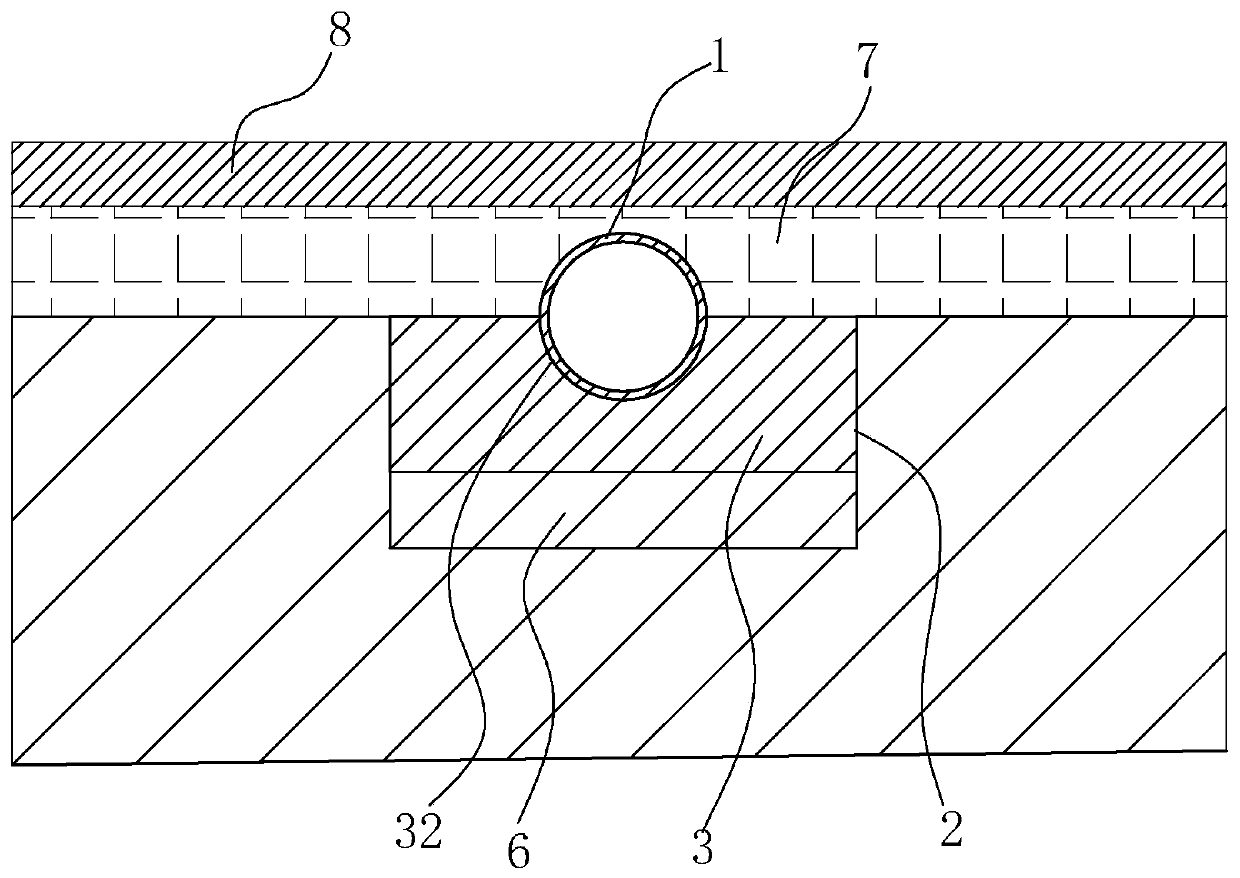
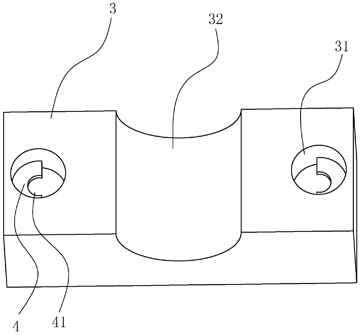
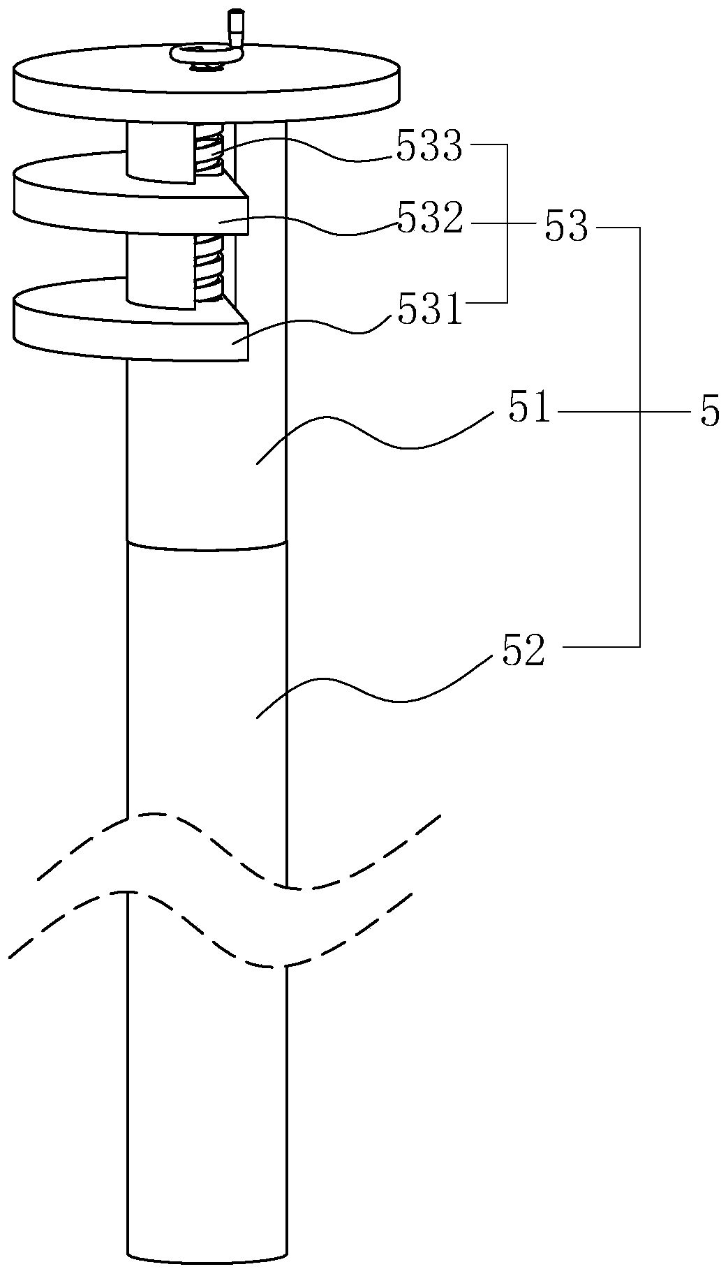
[0046] An installation structure for a drainage pipe, combined with figure 1 with Figure 4 , a groove 2 is opened on the ground, and the bottom of the groove 2 is formed by concrete pouring to form a concrete reinforcement layer 6, and a support seat 3 is installed on the top of the concrete reinforcement layer 6 along the extension direction of the groove 2, and the upper part of the support seat 3 The surface is laid with a pipe body 1, the pipe body 1 is provided with multiple sections, and the multi-section pipe bodies 1 are plugged and matched with each other. In the settling assembly 5 , a protective layer 7 and a cladding layer 8 are sequentially provided above the support base 3 from bottom to top, and the protective layer 7 completely submerges the top of the pipe body 1 . The concrete reinforcement layer 6 can tamp the bottom of the groove 2, and the support seat 3 can support and limit the pipeline body 1, so that the pipeline body 1 has high stability after layin...

Embodiment 2

[0057] The installation process of the drainage pipe includes the following steps:

[0058] S1, measuring and setting out and excavating trench 2: the excavation depth of trench 2 is 2.5-4.5 meters. In this embodiment, the preferred trench 2 depth is 4 meters, and trenches are excavated in relatively loose soil areas 2. Finally, drive steel piles into the groove wall of groove 2 to form a retaining wall structure. The driving depth of steel piles is 2-3 meters downward from the bottom of groove 2;

[0059] S2. Excavating the docking hole 21: measure and locate the position of the docking hole 21, dig out the docking hole 21, the excavation depth of the docking hole 21 is 0.5-2 meters, the preferred embodiment is 0.5 meters, and to the docking hole 21 Insert the mold column to isolate and protect the butt hole 21;

[0060] S3. Constructing the reinforced concrete layer 6: placing a reinforcement cage at the bottom of the trench 2 and pouring concrete to form the reinforced con...


PUM


Abstract

The invention relates to an installation structure for a drainage pipeline and an installation process thereof, and belongs to the technical field of drainage pipeline construction. The technical scheme of the installation structure for the drainage pipeline is as follows: a groove for laying the pipeline main body is arranged on the ground, the structure comprises a plurality of support bases arranged in the groove to support the pipeline main body; the support bases are provided with fixing holes vertically penetrating the support bases at the two sides of the pipeline main body; the inner walls of the fixing holes are provided with positioning rings, anti-sedimentation assemblies stretching below the bottom of the groove and in clamping match with the positioning rings to support the support bases are inserted into the fixing holes, so the effect of preventing the pipeline main body from settling and protecting the pipeline main body from damage due to settlement is achieved.

Description

technical field [0001] The invention relates to the technical field of drainage pipeline construction, in particular to the installation structure of the drainage pipeline and the installation process thereof. Background technique [0002] Drainage pipeline refers to the system composed of pipes and channels for collecting and discharging sewage, waste water and rainwater and their ancillary settings. With the gradual increase of urbanization, the construction requirements for urban drainage pipes are also getting higher and higher. [0003] The existing Chinese patent whose publication number is CN106978843A can be referred to, which discloses a municipal drainage pipeline construction process. Laying, inspection well masonry, closed water test, trench backfilling and pulling out steel sheet piles have the effects of improving the construction quality, reducing construction difficulty, shortening the construction period, and improving the safety of surrounding pipelines. ...

Claims


Application Information

Patent Timeline
Patent Type & Authority Applications(China)
IPC IPC(8): E03F3/00E03F3/04E03F3/06
CPCE03F3/00E03F3/04E03F3/06
Inventor 李伟森姚金龙关羽颜可壹
Owner 广州凌鼎建筑工程有限公司
Learn More