
A composite vortex reducer structure and a counter-rotating compressor system using the structure

A technology of vortex reducers and compressors, which is applied in the direction of machines/engines, parts of pumping devices for elastic fluids, mechanical equipment, etc., and can solve problems such as inapplicability

Active Publication Date: 2020-10-20
NANJING UNIV OF AERONAUTICS & ASTRONAUTICS
View PDF7 Cites 0 Cited by
  • Summary
  • Abstract
  • Description
  • Claims
  • Application Information

AI Technical Summary

Problems solved by technology

The existing vortex reducer structures are all arranged in the interstage disk cavity of the co-rotating compressor, which is not suitable for the engine structure of the counter-rotating compressor

Method used


Image

  • A composite vortex reducer structure and a counter-rotating compressor system using the structure
  • A composite vortex reducer structure and a counter-rotating compressor system using the structure
  • A composite vortex reducer structure and a counter-rotating compressor system using the structure

Examples


Embodiment Construction

[0031] The present invention will be further described below in conjunction with the accompanying drawings and embodiments.

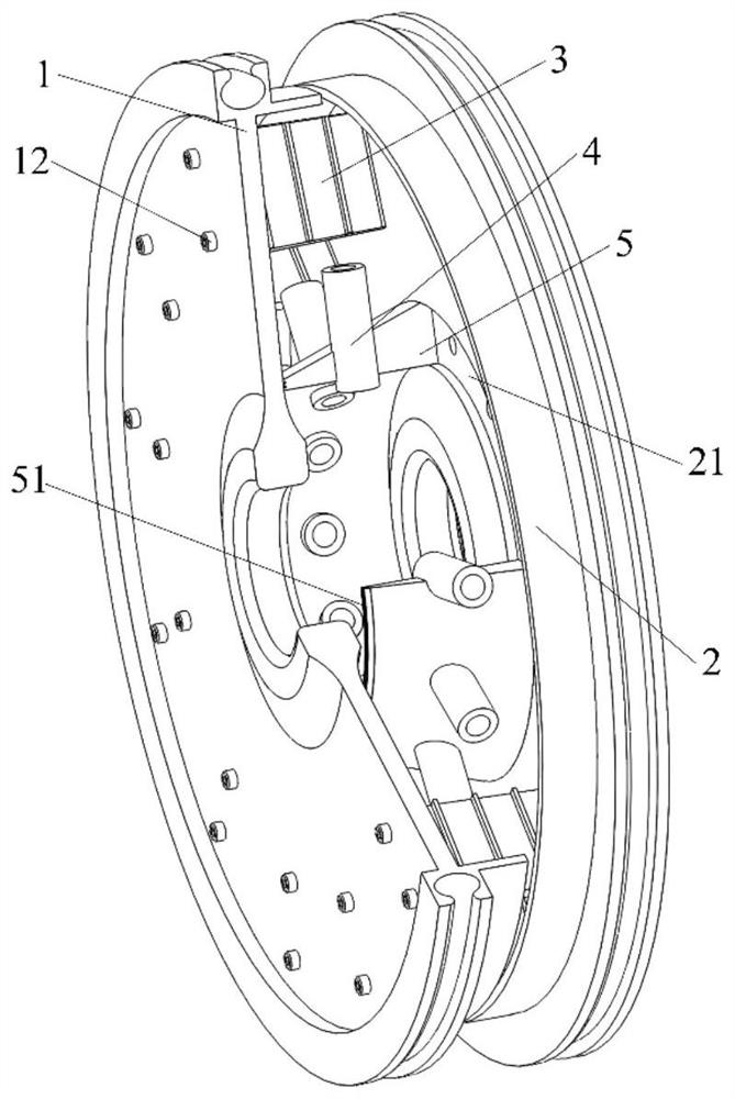
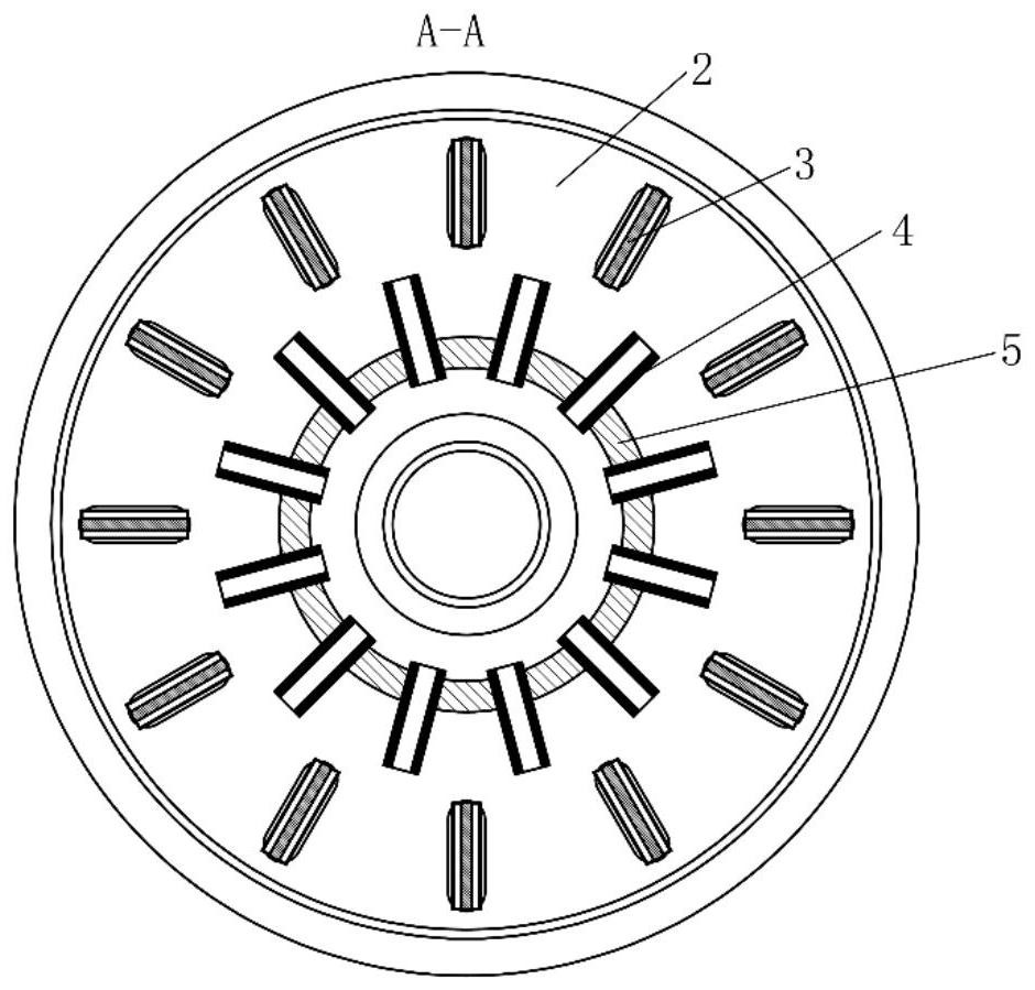
[0032] Such as figure 1 , 2a , 2b shows a composite vortex reducer structure, including the first-stage compressor wheel 1, the second-stage compressor wheel 2, the finned vortex reducer 3, the tubular vortex reducer 4 and the tubular vortex reducer Device holder 5;

[0033] Wherein, the finned vortex reducer 3, tubular vortex reducer 4 and tubular vortex reducer cage 5 are all arranged in the disk cavity between the primary compressor wheel 1 and the secondary compressor wheel 2 Inside, and the rotation axes of the first-stage compressor disc 1, the second-stage compressor disc 2, the finned vortex reducer 3, the tubular vortex reducer 4 and the tubular vortex reducer cage 5 coincide; the one The steering of the first-stage compressor wheel 1 and the second-stage compressor wheel 2 are opposite, forming a counter-rotating compressor structure, and t...


PUM


Abstract

The invention discloses a contra-rotating gas compressor structure and a composite type anti-whirling device structure suitable for a contra-rotating gas compressor air entraining system. The composite type anti-whirling device structure is characterized in that a first-stage gas compressor wheel disc and a second-stage gas compressor wheel disc reversely rotate in a coaxial manner, the contra-rotating gas compressor structure is formed, and outer edge check rings of the first-stage gas compressor wheel disc and the second-stage gas compressor wheel disc form the air inlet slot of the contra-rotating gas compressor air entraining system; fin type anti-whirling devices are evenly distributed on the high radius position along the circumference, and fixed to the first-stage gas compressor wheel disc, and tubular anti-whirling devices are evenly distributed on the low radius position along the circumference, and mounted on the second-stage gas compressor wheel disc through a tubular anti-whirling device holder. Through the composite type anti-whirling device structure of the high-radius fin type anti-whirling devices and the low-radius tubular anti-whirling devices, the airflow pressure losses of the contra-rotating gas compressor air entraining system can be effectively reduced, the system stability and reliability are greatly improved, meanwhile, the fixed manner is simple and reliable, mounting is convenient, and later-period maintenance and repair can be achieved.

Description

technical field [0001] The invention relates to a composite vortex reducer structure and a counter-rotating compressor system adopting the structure, belonging to the technical field of aero-engine structure design. Background technique [0002] As a complex rotating machine with a high degree of integration, an aero-engine consists of thousands of parts, mainly composed of rotating parts and stationary parts. Air is compressed in the compressor, combusted in the combustion chamber, and expanded to perform work in the turbine. Drives the turbine to rotate to provide power for the compressor. With the development of aero-engine design technology, in order to reduce the number of engine parts, reduce the weight of the engine, and improve the performance of the engine, a counter-rotating compressor structure is proposed. [0003] On the other hand, with the continuous improvement of engine performance, the temperature before the turbine inlet continues to increase, and the eff...

Claims


Application Information

Patent Timeline
Patent Type & Authority Patents(China)
IPC IPC(8): F04D29/26F04D29/66
CPCF04D29/26F04D29/666F04D29/667
Inventor 王锁芳夏子龙侯晓亭郝媛慧
Owner NANJING UNIV OF AERONAUTICS & ASTRONAUTICS
Learn More