Portable coupling

A shaft coupling, a portable technology, applied in the direction of shaft couplings, rigid shaft couplings, mechanical equipment, etc., can solve the problem that the coupling has no performance effect on the shaft, and cannot easily meet the demand, shaft or rotation Problems such as disengagement of parts, to achieve the effect of increasing the scope of use, uniform force, and balanced force

Active Publication Date: 2019-11-19
WENZHOU QIFANG NEW ENERGY CO LTD
View PDF3 Cites 2 Cited by
  • Summary
  • Abstract
  • Description
  • Claims
  • Application Information

AI Technical Summary

Problems solved by technology

[0004] (1) The traditional couplings are highly specific, and the advantages and disadvantages of different types are obvious. They cannot easily meet the working conditions with many demands, and need to be assisted by other mechanisms.
[0005] (2) In the process of transmitting motion and power, the traditional coupling still disengages the shaft or rotating parts, and finally fails to meet the required performance requirements
[0006] (3) When the traditional shaft coupling is connected to the long shaft, the shaft at the end not connected with the coupling is skewed downwards due to gravity and other factors, and finally it is not in a straight line with the shaft center of the coupling, resulting in the coupling The device does not have the proper performance effect on the shaft

Method used


Image

  • Portable coupling
  • Portable coupling
  • Portable coupling

Examples


Embodiment Construction

[0032] In order to make the technical means realized by the present invention, creative features, goals and effects easy to understand, the following combination Figure 1 to Figure 5 , to further elaborate the present invention.

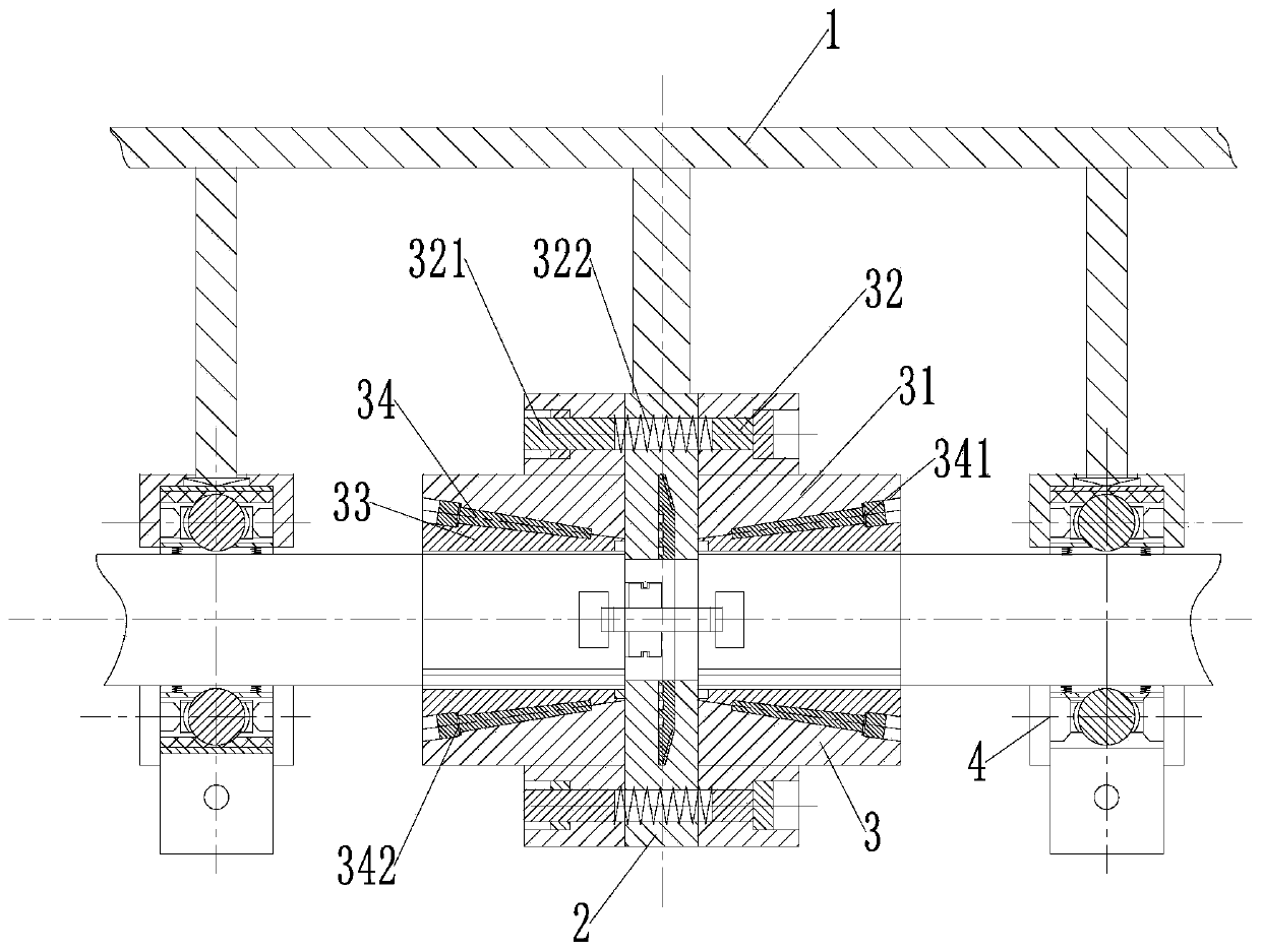
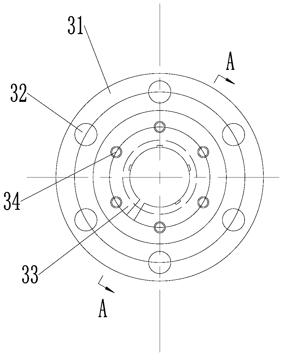
[0033] A convenient shaft coupling, including a bracket 1, a shaft fixing mechanism 2, a shaft coupling mechanism 3 and a bearing mechanism 4, the shaft fixing mechanism 2 is installed at the end of the rod in the middle of the bracket 1, and the left and right sides of the shaft fixing mechanism 2 are connected by screws Connected with the coupling mechanism, the ends of the rods on the left and right sides of the bracket 1 are equipped with bearing mechanisms 4; wherein:

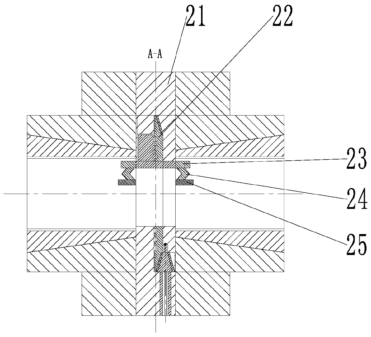
[0034] The fixed-axis mechanism 2 includes a fixed-axis housing 21, a three-jaw chuck 22, a fixed-axis fixing plate 23, a reed 24 and a large circular arc clamping plate 25, and the left and right ends of the fixed-axis housing 21 are uniformly provided with key grooves around t...


PUM


Abstract

The invention relates to a portable coupling. The portable coupling comprises a bracket, a fixed shaft mechanism, a shaft coupling mechanism and bearing mechanisms, wherein the fixed shaft mechanism is installed at the rod tail end of the middle of the bracket; the left side and the right side of the fixed shaft mechanism are connected with the shaft coupling mechanism through screws; the bearingmechanisms are installed at the rod tail ends of the left side and the right side of the bracket; the fixed shaft mechanism comprises a fixed shaft shell, a three-jaw chuck, a fixed shaft fixing plate, a spring leaf and a large arc clamping plate; the shaft coupling mechanism comprises a coupling shell, a spring screw, a conical bushing and a conical fastening piece; and each bearing mechanism comprises an omega-shaped fastening piece, a detachable ball bearing, a rubber ring and a telescopic spring plate. A shaft is fixed through the three-jaw chuck, so that the shaft is in coaxial matching,and the stress of the shaft is more uniform; and the conical bushing is matched with the conical fastening piece for use, the coupling can fix and clamp the shaft with multiple diameters, and finally,the purpose of improving the use effect of the coupling is achieved.

Description

technical field [0001] The invention relates to the transmission of shaft parts, in particular to a convenient coupling. Background technique [0002] Coupling is a mechanical part used to firmly connect the driving shaft and driven shaft in different mechanisms to rotate together and transmit motion and torque. The relative displacement of the two rotating components can be compensated by using the coupling, so that Reduce the manufacturing and installation errors between the connected components and improve the temperature change and load deformation during operation, etc., to compensate or alleviate the additional load between parts, the coupling also has the function of buffering and vibration reduction, so The coupling can protect the prime mover and the working machine from being damaged or not. It is widely used because of its safety, reliability, high strength and high service life, simple structure, convenient assembly and disassembly, and maintenance. [0003] Dur...

Claims


Application Information

Patent Timeline
Patent Type & Authority Applications(China)
IPC IPC(8): F16D1/04F16D1/05
CPCF16D1/04F16D1/05
Inventor 倪俊极张景龙张康乐
Owner WENZHOU QIFANG NEW ENERGY CO LTD
Why Eureka
Try Eureka