Mechanical seal end face for nuclear power medium-pressure safety injection pump

A technology for mechanical seals and pumps, which is applied in the direction of engine seals, mechanical equipment, engine components, etc., can solve the problems of increased leakage of mechanical seals, achieve the effects of enhanced lubricity, increased liquid film thickness, and reduced leakage

Pending Publication Date: 2019-11-19
DANDONG COLOSSUS GROUP
View PDF0 Cites 0 Cited by
  • Summary
  • Abstract
  • Description
  • Claims
  • Application Information

AI Technical Summary

Problems solved by technology

However, although this technology improves the service life of the sealing end face, another problem is that the leakage of the mechanical seal increases.
Most of the leakage of the mechanical seal that drives the pressure groove in the prior art is 50-200ml / h, which is difficult to meet the strict requirements on the leakage

Method used


Image

  • Mechanical seal end face for nuclear power medium-pressure safety injection pump
  • Mechanical seal end face for nuclear power medium-pressure safety injection pump

Examples


Embodiment 1

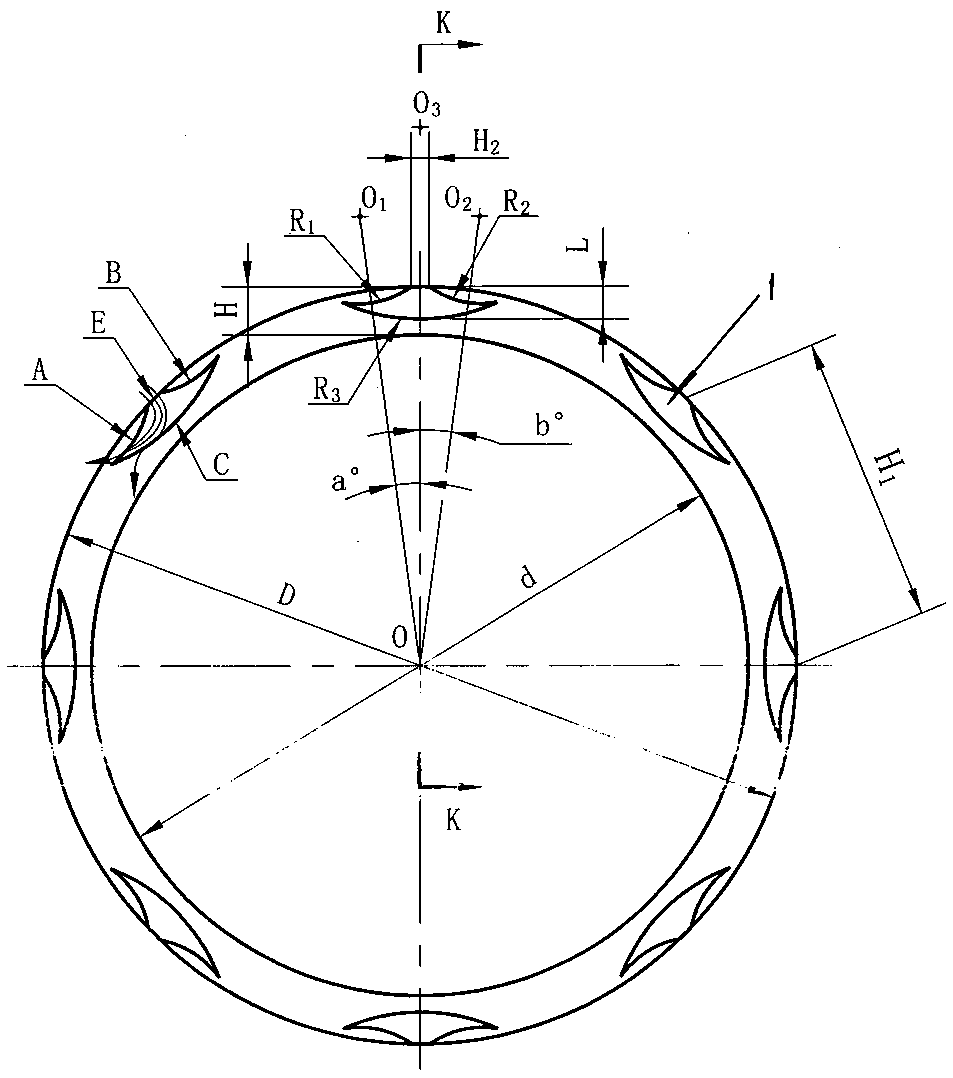
[0028] Technical parameters: the inner diameter of the friction end face d=106mm, the outer diameter of the friction end face D=114mm, the width of the end face H=4mm; the inner arc edge C radius R 3 =25mm; Radius R of left outer arc edge A 1 Radius R with the right outer arc edge B 2 :R 1 =R 2 =10mm; notch E width H 2 ≈3.5mm; the distance between the arc top of the center line of the inner arc side C and the outer circle of the friction end face is L=2.8mm; the angle a between the center of the left outer arc side A and the center b of the right outer arc side B: a= b=6º; the distance H between the centers of two adjacent arc-shaped dynamic pressure grooves 1 1 =25mm; depth of dynamic pressure groove h=6μm; number of dynamic pressure grooves n=14.

[0029] Working conditions: 180°C water; pressure 0.5MPa; speed 1500r / min; running time: 100 hours.

[0030] Test method: Simulate the above-mentioned working conditions on the test bench to conduct an operation test, observe...

Embodiment 2

[0033] Technical parameters: the inner diameter of the friction end face d=106mm, the outer diameter of the friction end face D=114mm, the width of the end face H=4mm; the inner arc edge C radius R 3 =20mm; Radius R of left outer arc edge A 1 Radius R with the right outer arc edge B 2 :R 1 =R 2 =8mm; notch E width H 2 ≈3mm; the distance between the arc top of the center line of the inner arc side C and the outer circle of the friction end face is L=2.8mm; the angle a between the center of the left outer arc side A and the center b of the right outer arc side B: a=b =6.5º; the distance H between the centers of two adjacent arc-shaped dynamic pressure grooves 1 1 =20mm; depth of dynamic pressure groove h=5μm; number of dynamic pressure grooves n=18.

[0034] Working conditions: 180°C water; pressure 2MPa; speed 3000r / min; running time: 100 hours.

[0035] Test method: Simulate the above-mentioned working conditions on the test bench to conduct an operation test, observe th...

Embodiment 3

[0038] Technical parameters: the inner diameter of the friction end face d=106mm, the outer diameter of the friction end face D=114mm, the width of the end face H=4mm; the inner arc edge C radius R 3 =22mm; Radius R of left outer arc edge A 1 Radius R with the right outer arc edge B 2 :R 1 =R 2 =9mm; notch E width H 2 ≈3mm; the distance between the arc top of the center line of the inner arc side C and the outer circle of the friction end face is L=2.8mm; the angle a between the center of the left outer arc side A and the center b of the right outer arc side B: a=b =6º; the distance H between the centers of two adjacent arc-shaped dynamic pressure grooves 1 1 =22mm; depth of dynamic pressure groove h=8μm; number of dynamic pressure grooves n=16.

[0039] Working conditions: 180°C water; pressure 6MPa; speed 1000r / min; running time: 100 hours.

[0040] Test method: Simulate the above-mentioned working conditions on the test bench to conduct an operation test, observe the ...


PUM


Abstract

The invention discloses a mechanical seal end face for a nuclear power medium-pressure safety injection pump. Arc-shaped dynamic pressure grooves (1) are uniformly distributed on the circumference ofthe friction end face of a dynamic friction ring or a static friction ring of a mechanical seal, and the arc-shaped dynamic pressure grooves (1) are arc-shaped grooves each formed by an inner side circular arc edge (C), a left outer side circular arc edge (A), a right outer side circular arc edge (B) and a liquid inlet notch (E), wherein the left outer side circular arc edge (A) and the right outer side circular arc edge (B) are symmetrical. Under the working conditions that the medium hot water temperature is 180 DEG C, pressure is 0.5-6 MPa, the rotating speed is 1000-3000r/min, and no cooling measure is adopted, the sealing leakage amount reaches 5-10 ml/h, the service life reaches 25000h, the use requirement of the nuclear power medium-pressure safety injection pump is fully met, and the service life of the mechanical seal is prolonged.

Description

technical field [0001] The invention relates to a mechanical seal, in particular to the improvement of the end face of the mechanical seal, which is applied to the 180°C hot water medium working condition without cooling measures, especially for the mechanical seal end face of a nuclear power medium-pressure safety injection pump. Background technique [0002] The traditional contact mechanical seal is characterized by stable performance and low leakage. The friction state of the end face of the contact mechanical seal is relatively complicated, which belongs to the mixed friction state. From a microscopic point of view, the contact surface of both ends has a certain roughness, and there are high points and low points. The gap between the storage medium and the so-called liquid film will be formed. The thickness of the liquid film is about 0.5-1 μm. [0003] For media with low boiling point and easy vaporization, especially for high-temperature hot water without cooling dev...

Claims


Application Information

Patent Timeline
Patent Type & Authority Applications(China)
IPC IPC(8): F16J15/40
CPCF16J15/40
Inventor 梅义宽臧祖玄臧蕴棋纪德宏方明欣
Owner DANDONG COLOSSUS GROUP
Why Eureka
Try Eureka