
Brightness compensation method, brightness compensation circuit and display device

A brightness compensation and display technology, applied to static indicators, instruments, etc., can solve the problems of cost increase, long switching time, size and cost increase, etc., and achieve the effect of size reduction and short switching time

Active Publication Date: 2019-11-19
WUHAN TIANMA MICRO ELECTRONICS CO LTD
View PDF7 Cites 11 Cited by
  • Summary
  • Abstract
  • Description
  • Claims
  • Application Information

AI Technical Summary

Problems solved by technology
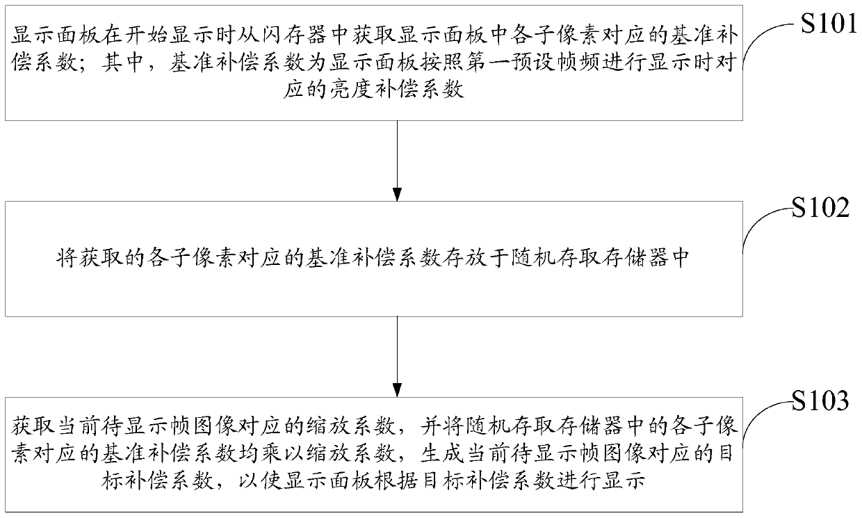
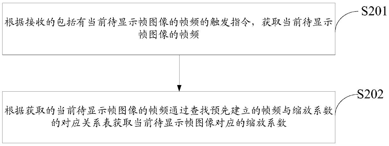
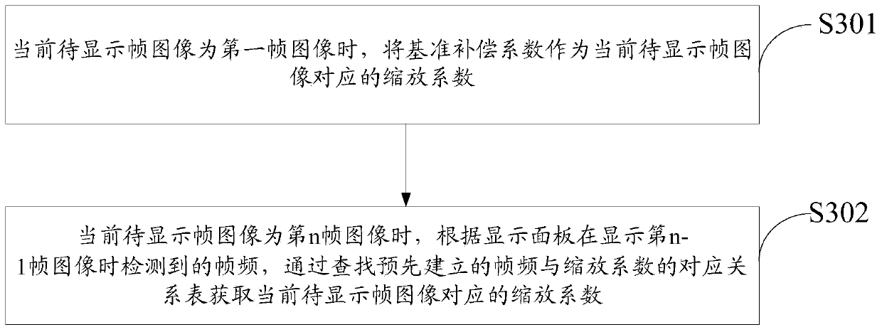
However, the above two methods have the following technical problems: 1. It is necessary to store two sets of Demura compensation coefficients, and the space of the Flash will be doubled, and the cost will be increased; 2. The RAM size of the DDIC will be doubled, and the size and cost of the DDIC will increase. Increase; 3. When switching the frame rate, because the Demura compensation coefficient needs to be reloaded, it needs to go through the process of turning off the screen → erasing data → reloading data → turning on the screen, so the switching time is longer, and the screen needs to be turned off. poor user experience

Method used


Image

  • Brightness compensation method, brightness compensation circuit and display device
  • Brightness compensation method, brightness compensation circuit and display device
  • Brightness compensation method, brightness compensation circuit and display device

Examples


Embodiment Construction

[0026] In order to make the above objects, features and advantages of the present invention more comprehensible, the present invention will be further described below in conjunction with the accompanying drawings and embodiments. Example embodiments may, however, be embodied in many forms and should not be construed as limited to the embodiments set forth herein; rather, these embodiments are provided so that this disclosure will be thorough and complete, and will fully convey the concept of example embodiments to those skilled in the art. The same reference numerals denote the same or similar structures in the drawings, and thus their repeated descriptions will be omitted. The words expressing position and direction described in the present invention are all described by taking the accompanying drawings as an example, but changes can also be made according to needs, and all changes are included in the protection scope of the present invention. The drawings of the present inv...


PUM


Abstract

The invention discloses a brightness compensation method, a brightness compensation circuit and a display device. The brightness compensation method includes the steps: a display panel acquires a reference compensation coefficient from a flash memory at the beginning of display; the obtained reference compensation coefficient is stored in a random access memory; and finally, a scaling coefficientcorresponding to the current to-be-displayed frame image is obtained, and the reference compensation coefficient corresponding to each sub-pixel in the random access memory is multiplied by the scaling coefficient to generate a target compensation coefficient corresponding to the current to-be-displayed frame image and display according to the target compensation coefficient. By means of the compensation method, no matter how many frame frequencies are supported by the display panel, as only the reference compensation coefficients need to be stored in the random access memory and the flash memory, compared with an existing driving method, the size can be reduced by at least one time, and when the frame frequency is switched, the target compensation coefficient can be obtained only by multiplying the reference compensation coefficient by the scaling coefficient, and the compensation coefficient does not need to be reloaded, so that the switching time is short, and a screen does not needto be turned off.

Description

technical field [0001] The invention relates to the field of display technology, in particular to a brightness compensation method, a brightness compensation circuit and a display device. Background technique [0002] The organic light-emitting display panel has different threshold values ​​due to different crystallization degrees of low-temperature polysilicon transistors, and the film thickness of the entire display panel is not completely uniform, and the final result is display unevenness (mura). OLED display panels need to eliminate display unevenness (demura) before leaving the factory. Since the demura coefficients corresponding to different frame rates are not the same, there are two methods in the prior art. Take the display panel that can display two frame rates as an example: one of them is to store two sets of Demura compensation coefficients in the flash memory (Flash), and when the display panel is turned on, the two sets (such as 60Hz and 90Hz) can be simulta...

Claims


Application Information

Patent Timeline
IPC IPC(8): G09G3/3208
CPCG09G3/3208G09G2320/0233G09G3/3225G09G2320/0285G09G2340/0435G09G3/3283G09G2300/0842G09G2330/027G09G2360/147
Inventor 李军余志华
Owner WUHAN TIANMA MICRO ELECTRONICS CO LTD
Features
  • Generate Ideas
  • Intellectual Property
  • Life Sciences
  • Materials
  • Tech Scout
  • Unparalleled Data Quality
  • Higher Quality Content
  • 60% Fewer Hallucinations
Learn More