Optical splitter and single-fiber bidirectional passive optical network transmission system

An optical splitter and optical splitting technology, applied in the field of optical communication, can solve the problems of coupling power loss and optical power loss that cannot reach the range of OLT receiving optical power, and achieve the effect of zero loss

Active Publication Date: 2019-11-19
BEIJING JISHI HUITONG TECH CO LTD
View PDF5 Cites 2 Cited by
  • Summary
  • Abstract
  • Description
  • Claims
  • Application Information

AI Technical Summary

Problems solved by technology

In the downlink broadcast direction, optical amplifiers can be added between the OLT and the optical splitter to achieve transmission to 1024 households or more; but in the uplink direction, adding optical amplifiers on the user side is limited by factors such as cost. It is not feasible, which leads to the unavoidable power loss of optical centralized coupling from the user side to the network side, and the excessive optical power loss cannot reach the received optical power range of the OLT, which leads to the fact that a single OLT PON port in the uplink direction can generally only transmit 32 households or 64 households

Method used


Image

  • Optical splitter and single-fiber bidirectional passive optical network transmission system
  • Optical splitter and single-fiber bidirectional passive optical network transmission system
  • Optical splitter and single-fiber bidirectional passive optical network transmission system

Examples


Embodiment Construction

[0038] Various exemplary embodiments, features, and aspects of the present disclosure will be described in detail below with reference to the accompanying drawings. The same reference numbers in the figures indicate functionally identical or similar elements. While various aspects of the embodiments are shown in drawings, the drawings are not necessarily drawn to scale unless specifically indicated.

[0039] The word "exemplary" is used exclusively herein to mean "serving as an example, embodiment, or illustration." Any embodiment described herein as "exemplary" is not necessarily to be construed as superior or better than other embodiments.

[0040] In addition, in order to better illustrate the present disclosure, numerous specific details are given in the following specific implementation manners. It will be understood by those skilled in the art that the present disclosure may be practiced without some of the specific details. In some instances, methods, means, componen...


PUM


Abstract

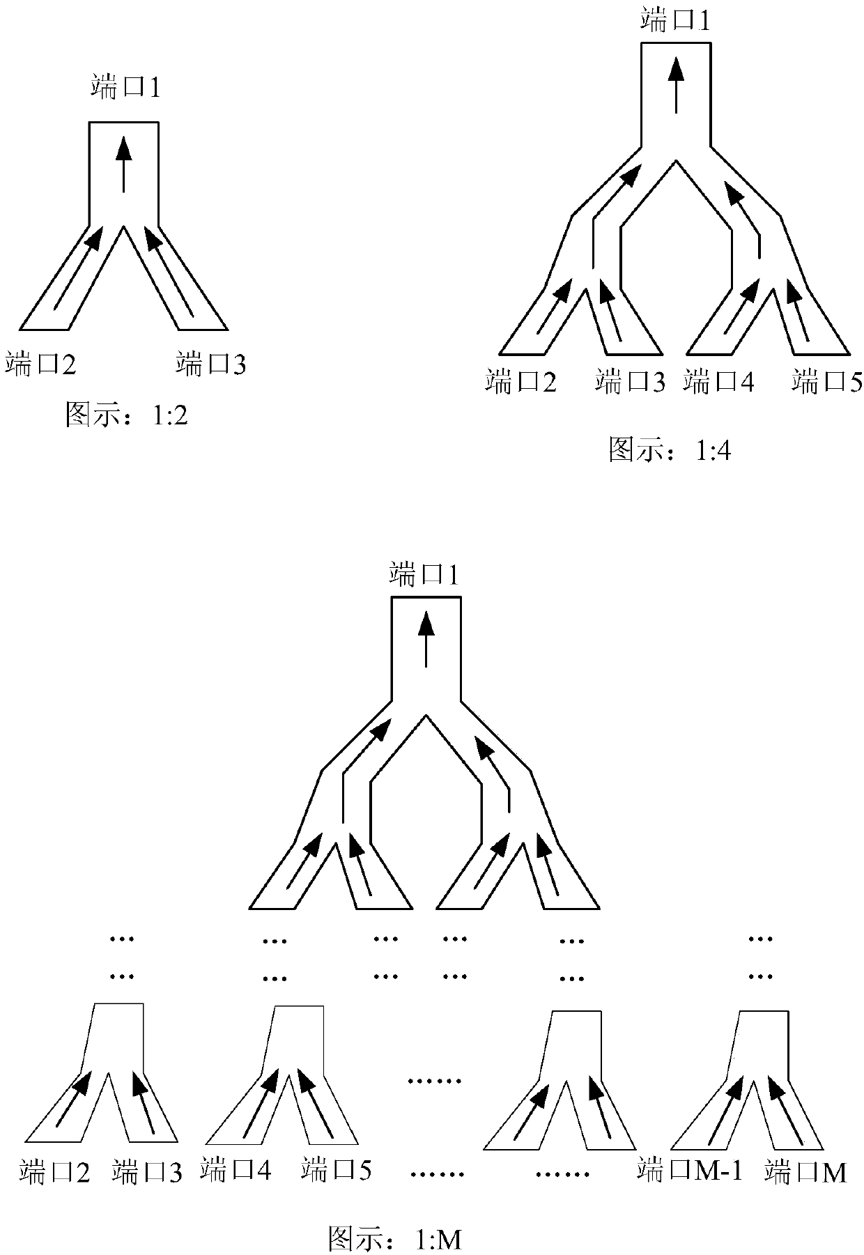
The invention relates to an optical splitter and a single-fiber bidirectional passive optical network transmission system. The optical splitter comprises one or more optical branching units; each optical branching unit comprises two input channels, an output channel and an optical coupling structure, wherein the optical coupling structure is arranged in a coupling area of the optical branching unit, the optical coupling structure can couple the optical waves input by the two input channels into one path of optical waves in a lossless manner; and one path of coupled light wave is output throughthe output channel. By adding the optical coupling structure in the optical splitter; according to the optical splitter and the single-fiber bidirectional passive optical network transmission systemprovided by the embodiment of the invention, when the optical splitter couples uplink data in a centralized manner, zero loss of optical power is realized.

Description

technical field [0001] The present disclosure relates to the field of optical communication, in particular to an optical splitter and a single-fiber bidirectional passive optical network transmission system. Background technique [0002] Passive Optical Network (PON, Passive Optical Network) is a single-fiber bidirectional optical access network using a point-to-multipoint (P2MP, Point to Multi-Point) structure. The PON system consists of an optical line terminal (OLT, optical line terminal) at the central office, an optical distribution network (ODN, optical distribution network) and an optical network unit (ONU, Optical Network Unit) at the user side, and is a single-fiber bidirectional system. In the downlink direction (OLT to ONU), the signal sent by the OLT reaches each ONU through the ODN. In the upstream direction (ONU to OLT), the signal sent by the ONU will only reach the OLT, and will not reach other ONUs. The ODN provides an optical channel between the OLT and t...

Claims


Application Information

Patent Timeline
Patent Type & Authority Applications(China)
IPC IPC(8): H04Q11/00H04B10/80H04B10/25
CPCH04B10/25H04B10/801H04Q11/0067
Inventor 张学军照尔格图欧阳捷
Owner BEIJING JISHI HUITONG TECH CO LTD
Why Eureka
Try Eureka