Cell discharge control circuit

A control circuit and battery discharge technology, applied in battery circuit devices, battery over-discharge protection, circuit devices, etc., can solve the problems of battery over-discharge, affecting battery use, and large static current of the protection board, so as to reduce standby current, The effect of improving the service life

Inactive Publication Date: 2016-11-16
苏州能率电子科技有限公司
View PDF4 Cites 0 Cited by
  • Summary
  • Abstract
  • Description
  • Claims
  • Application Information

AI Technical Summary

Problems solved by technology

[0003] The quiescent current of the protection board is too large. After the product is placed for a long time, the battery will be drained, causing the battery to be over-discharged, which will affect the use of the battery. Even if the battery can be reactivated, the battery cycle life will be shortened.

Method used


Image

  • Cell discharge control circuit

Examples


Embodiment Construction

[0023] The specific implementation manners of the present invention will be further described below in conjunction with the drawings and examples. The following examples are only used to illustrate the technical solution of the present invention more clearly, but not to limit the protection scope of the present invention.

[0024] The technical scheme of concrete implementation of the present invention is:

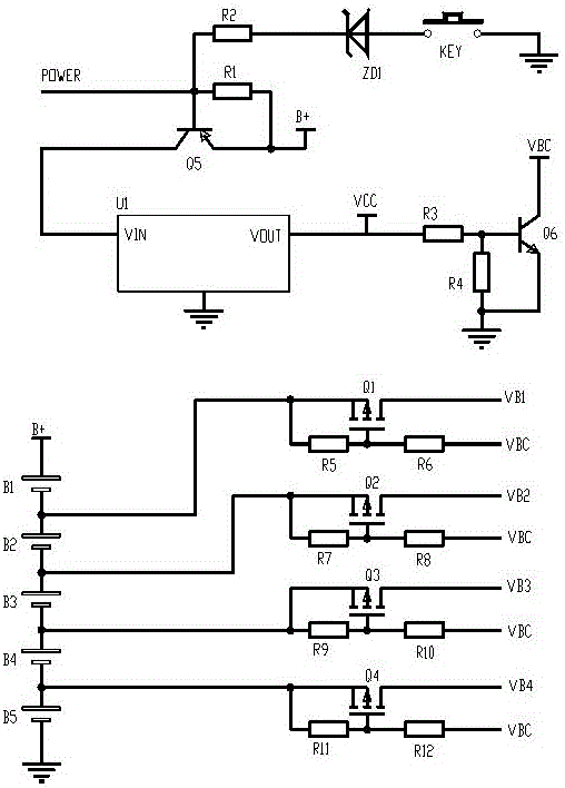
[0025] Such as figure 1 As shown, a battery discharge control circuit includes: the first battery B1, the second battery B2, the third battery B3, the fourth battery B4 and the fifth battery B5 connected in series in sequence, the first MOS transistor Q1, the second MOS transistor Q2, the third MOS transistor Q3, the fourth MOS transistor Q4, the PNP transistor Q5, the NPN transistor Q6, the low dropout linear regulator U1, and the microcontroller;

[0026] The low dropout linear voltage regulator U1 includes: an input terminal VIN, a ground terminal, and an output termi...


PUM


Abstract

The invention discloses a cell discharge control circuit which comprises a first cell, a second cell, a third cell, a fourth cell, a fifth cell, a first MOS, a second MOS, a third MOS, a fourth MOS, a PNP triode, an NPN triode, a low differential pressure linear voltage regulator, and a single-chip microcomputer in a series connection. According to the cell discharge control circuit, the standby current can be substantially reduced, and the service lives of the cells are improved.

Description

technical field [0001] The invention relates to a battery discharge control circuit. Background technique [0002] At present, most of the microcontrollers on the market use the sleep mode to minimize the quiescent current of the protection board when it is in standby. However, the single-chip microcomputer is in a sleep state and cannot shut down the battery circuit. The standby current is generally 1-3mA. In this case, the battery capacity of 2Ah is calculated. Assuming that the standby current is 2mA, the battery will be emptied after 1000h in the storage state. [0003] The quiescent current of the protection board is too large, and the battery will be drained after the product is placed for a long time, resulting in over-discharge of the battery, which will affect the use of the battery. Even if the battery can be reactivated, the battery cycle life will be shortened. Contents of the invention [0004] The object of the present invention is to provide a battery disch...

Claims


Application Information

Patent Timeline
Patent Type & Authority Applications(China)
IPC IPC(8): H02J7/00
CPCH02J7/0029H02J7/00306H02J7/0063H02J2007/0067H02J2207/10
Inventor 卜敏
Owner 苏州能率电子科技有限公司
Why Eureka
Try Eureka