Solar street lamp control device with energy-saving function
A solar street lamp and control device technology, which is applied in energy-saving control technology, lighting device, electric lamp circuit layout, etc., can solve the problem that solar energy is not widely used in street lamps, and achieve the effect of ensuring normal operation.
- Summary
- Abstract
- Description
- Claims
- Application Information
AI Technical Summary
Problems solved by technology
Method used
Image
Examples
Embodiment 1
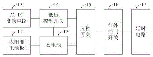
[0019] figure 1 It is a structural schematic diagram of a solar street light control device with energy-saving function according to an embodiment of the present invention. The solar street light control device with energy-saving function includes a solar panel 11, a battery 12, an AC-DC conversion circuit 13, and a low-voltage control switch 14. , Light control switch 15, infrared control switch 16, and delay circuit 17.
[0020] Specifically, the storage battery 12 is connected to the solar panel 11 and the light control switch 15. The solar panel 11 converts solar energy into electric energy, and charges the storage battery 12. The storage battery 12 is charged by the solar panel 11 to provide a first power supply voltage to the light-controlled switch 15. The low voltage control switch 14 is connected to the AC-DC conversion circuit 13, the battery 12, and the light control switch 15. The AC-DC conversion circuit 13 is used to convert the AC voltage into a stable second powe...
Embodiment 2
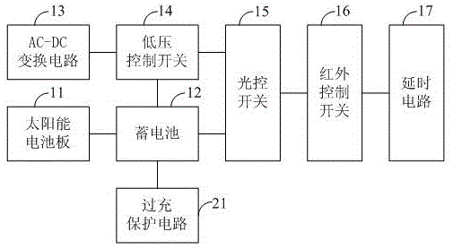
[0024] figure 2 It is a schematic structural diagram of a solar street lamp control device with energy-saving function according to another embodiment of the present invention. The difference between this embodiment and Embodiment 1 is that it also includes an overcharge protection circuit 21 connected to the battery 12. By providing the overcharge protection circuit 21, it is possible to prevent the solar panel 11 from overcharging the storage battery 12, so as to prolong the service life of the storage battery 12.
Embodiment 3
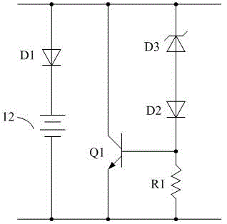
[0026] image 3 It is a circuit diagram of an overcharge protection circuit 21 according to an embodiment of the present invention. The overcharge protection circuit 21 includes an anti-reverse diode D1, a Zener diode D3, a bias diode D2, a current limiting resistor R1, and an NPN transistor Q1.
[0027] Specifically, the cathode of the anti-reverse diode D1 is connected to the anode of the battery 12, and the anode of the anti-reverse diode D1 is connected to the collector of the NPN transistor Q1 and the cathode of the Zener diode D3. The anode of the diode D3 is connected to the anode of the bias diode D2, the cathode of the bias diode D2 is connected to the base of the NPN transistor Q1 and one end of the current limiting resistor R1, and the other end of the current limiting resistor R1 Connect the emitter of the NPN transistor Q1 and the negative electrode of the battery 12.
[0028] The NPN transistor Q1, the bias diode D2, and the Zener diode D3 form a protection circuit, a...
PUM
 Abstract
Description
Claims
Application Information
 - R&D
- Intellectual Property
- Life Sciences
- Materials
- Tech Scout
- Unparalleled Data Quality
- Higher Quality Content
- 60% Fewer Hallucinations
Browse by: Latest US Patents, China's latest patents, Technical Efficacy Thesaurus, Application Domain, Technology Topic, Popular Technical Reports.
© 2025 PatSnap. All rights reserved.Legal|Privacy policy|Modern Slavery Act Transparency Statement|Sitemap|About US| Contact US: help@patsnap.com


