Multifunctional rope unwinding device

A multi-functional and equipment technology, which is used in the field of fire fighting, rescue and escape equipment outside the building, and can solve the problems of large volume and weight of slow-down ropes, great influence, and occupation of building structures.

Pending Publication Date: 2019-11-22
福州市晋安区澳榕自动化设备有限公司
View PDF0 Cites 0 Cited by
  • Summary
  • Abstract
  • Description
  • Claims
  • Application Information

AI Technical Summary

Problems solved by technology

[0022] After studying the use process of the above-mentioned existing descending device and the user's feelings, it is found that the existing descending device with the descending rope has many shortcomings: this descending device is provided on the floor of the fire place to provide This floor is used by escape personnel, because this floor is the ignition point of fire, which is a threat to the descending device suspended on this floor, and the existing descending device needs to be inspected regularly. Generally, individual buyers lack this awareness due to troubles, which also poses a threat to The normal use of the descending device has caused potential hidden dangers, and there have been casualty accidents using the descending device; the descending height of the existing descending devices with descending ropes is controlled below 100 meters. The volume and weight of the descending device is large, and it is difficult for individual users to hang it on the window, and the descending rope with a length of more than 100 meters is large in size and weight. It is not only difficult for the user to throw such a descending rope downward, but also because Due to the tail effect, the dropped slow-down rope will also accidentally injure the people under the building or the glass of the outer wall. At the same time, the weight and impact of the dropped slow-down rope will also cause damage to the internal structure of the slow-down device.
Moreover, many existing escape products and escape rescue programs have caused many adverse effects on the original building, such as occupying the area of ​​the building or occupying the distance between buildings, or having a great impact on the structure of the original building, etc.

Method used


Image

  • Multifunctional rope unwinding device
  • Multifunctional rope unwinding device
  • Multifunctional rope unwinding device

Examples


Embodiment Construction

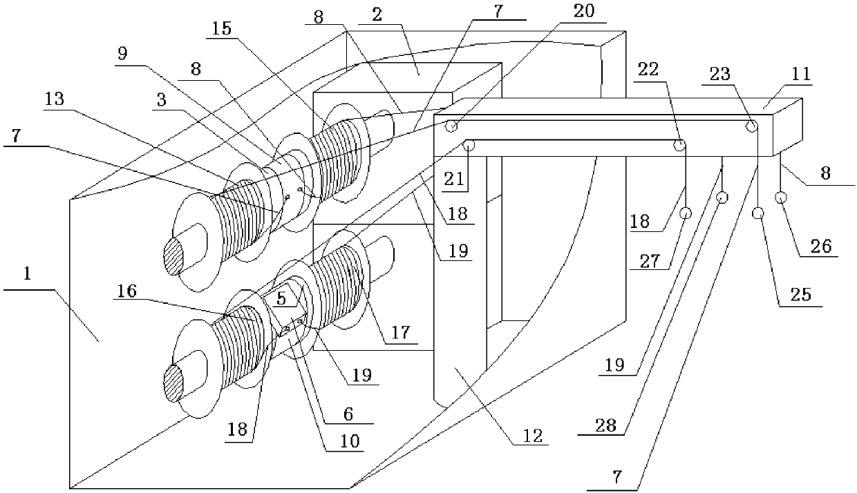
[0111] Such as figure 1 as shown, figure 1 It is a schematic oblique view of the multifunctional rope releasing device according to the first embodiment of the present application. The multifunctional rope-releasing device includes a housing 1, an electric motor 2, a rotating shaft 3, a rotating shaft 5, a descending device 6, a pull rope 7, a pull rope 8, a rotating ring body 9, a rotating ring body 10, a cantilever 11, and a column 12 , the above-mentioned electric motor 2, rotating shaft 3, rotating shaft 5, slow descender 6, stay rope 7, stay rope 8, rotating ring body 9, rotating ring body 10, column 12 are arranged in the housing, electric motor 2 and rotating shaft 3, rotating shaft The 5 connection can drive the rotating shaft 3 and the rotating shaft 5 to rotate. The above-mentioned rotating ring body 9 is sleeved on the outer circumference of the rotating shaft 3 and can rotate around the rotating shaft 3. The above-mentioned rotating ring body 10 is sleeved on th...


PUM


Abstract

Provided is a multifunctional rope unwinding device. The multifunctional rope unwinding device comprises an electric power transmission system or a hydraulic transmission system or a pneumatic transmission system, a coiling block and a slow descending device; a rotating shaft of a motor of the electric power transmission system or the hydraulic transmission system or the pneumatic transmission system is connected with the coiling block and can be used for driving the coiling block to rotate; a rotating ring body is connected to a coiling block shaft of the coiling block, can only rotate in onedirection and is locked in the other direction and cannot rotate; the slow descending device is arranged on the rotating ring body; a slow descending rope extending out of the slow descending deviceis wound on the coiling block and extends out of the coiling block to be directly connected with a heavy object or connected with the heavy object after penetrating through a wire groove of a direction changing pulley; the structure of the heavy object includes that a rubber ball or a fixed pulley or a movable pulley is adopted; and a cable connected with an electromotor is connected with a powersource through an electrical control system.

Description

technical field [0001] The application belongs to a kind of outdoor fire extinguishing, rescue and escape equipment used in the construction field. Background technique [0002] Fires in high-rise buildings have always attracted people's attention, and the reliability of fire elevators in the event of a fire is worth pondering. There is also the arm-raising fire truck used in the existing fire-fighting and lifesaving, which can generally implement fire fighting and rescue at a height of 53 meters, and the climbing of the fire-fighting ladder truck has a limit. Usually, the fire-fighting ladder truck can only rise to 80 of the limit value. % or so, if the wind force on the ground reaches level 4 to 5, the fire-fighting aerial ladder truck will not be able to raise the operation. In this way, once a high-rise building above 50 meters catches fire or people are trapped, it will be difficult for the fire-fighting aerial ladder to play a role. Rely on one's own ability to escape...

Claims


Application Information

Patent Timeline
IPC IPC(8): A62B1/10A62B1/12A62B1/18A62C31/00
CPCA62B1/10A62B1/12A62B1/18A62C31/00
Inventor 不公告发明人
Owner 福州市晋安区澳榕自动化设备有限公司
Why Eureka
Try Eureka