
Casting core structure

A sand core and casting technology, applied in the field of foundry, can solve the problems of reduced yield, increased pouring weight, and slotted casting, etc., and achieves the effects of small gap, good contact, and increased extrusion force.

Active Publication Date: 2019-11-22
KOCEL STEEL
View PDF5 Cites 4 Cited by
  • Summary
  • Abstract
  • Description
  • Claims
  • Application Information

AI Technical Summary

Problems solved by technology

[0002] The production of steel castings generally adopts the scheme of real sample molding or core molding. In the prior art, the dimensional accuracy of the sand core is low, and the mating surface of the sand core is a flat or curved surface. The mating surface of the sand core is generally There are many uneven phenomena, which lead to a large gap in the sand core during the core assembly process. During the casting process, the molten steel will flow along the gap between the mating surfaces of the sand core, resulting in a large number of draped casting defects. In severe cases, it will Spill, resulting in loss of molten steel
Larger gaps in the process of sand core assembly will form larger cumulative deviations in size, resulting in unqualified casting sizes after casting; draping casting defects will increase the wall thickness or contour of the casting, and the casting weight will increase. The rate is reduced, and the yield rate is the ratio of casting weight to pouring weight

Method used


Image

  • Casting core structure
  • Casting core structure
  • Casting core structure

Examples


Embodiment 1

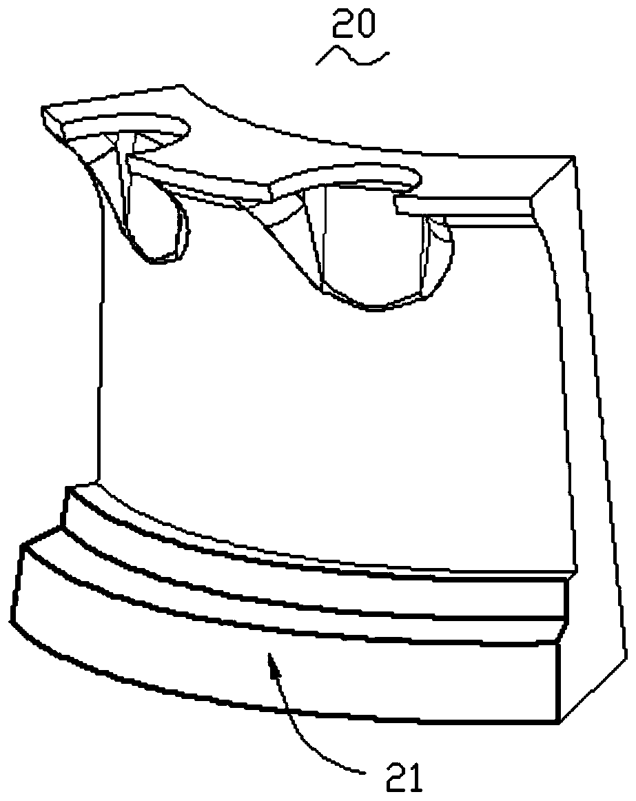
[0022] Example 1: A casting sand core structure, please refer to the attached Figure 1 to 3 As shown, it includes: a sand core 10 and a sand core 20 that are attached to each other, the sand core 10 has a sand core a mating surface 11 that is attached to the sand core 20, and the sand core 20 has The second mating surface 21 of the sand core which is attached to the sand core 10, the first mating surface 11 of the sand core is stepped, and the second mating surface 21 of the sand core is engaged with the first mating surface 11 of the sand core Stepped.

[0023] It should be noted that the sand core-matching surface 11 is stepped, and the sand core-matching surface 21 is stepped into the sand core-matching surface 11; that is, the sand core-matching surface 11 The two mating surfaces 21 with the sand core are multiple planes or curved surfaces. According to the stepped staggered design, there are multiple contact surfaces between the sand core 10 and the sand core 2 after the c...

Embodiment 2

[0024] Example 2: A sand core structure for castings, please see attached Figure 1 to 3 As shown, it includes: a sand core 10 and a sand core 20 that are attached to each other, the sand core 10 has a sand core a mating surface 11 that is attached to the sand core 20, and the sand core 20 has The second mating surface 21 of the sand core that is attached to the sand core 10, the first mating surface 11 of the sand core is stepped, and the second mating surface 21 of the sand core is fitted with the first mating surface 11 of the sand core Stepped.

[0025] It should be noted that the sand core-matching surface 11 is stepped, and the sand core-matching surface 21 is stepped to fit the sand core-matching surface 11; that is, the sand core-matching surface 11 The two mating surfaces 21 with the sand core are multiple planes or curved surfaces. According to the stepped staggered design, there are multiple contact surfaces between the sand core 10 and the sand core 2 after the core ...


PUM

PropertyMeasurementUnit
Diameteraaaaaaaaaa

Abstract

The invention belongs to the technical field of casting, and particularly relates to a casting core structure. The casting core structure comprises a first core and a second core which are attached toeach other. The matched faces of the first core and the second core are the first core matched face and the second core matched face. The first core matched face is in a step shape, and the second core matched face is in a step shape matched with the first core matched face. In the core assembling process, the matched sides of the matched faces of the two attached cores are each provided with a through groove so that the two attached cores can form a cavity structure after being assembled and meshed. A metal rod is arranged in the cavity structure; in the casting process, when molten steel flows along the core matched faces to make contact with the metal rod, under the cooling effect of the metal rod, the molten steel is solidified and prevented from continuously flowing. By means of thecore structure and a core assembling method, seams produced in the core assembling process can be avoided or reduced, fins generated after pouring is completed are avoided, the loss of the molten steel is reduced, the yield is increased, and the casting quality is improved.

Description

Technical field [0001] The invention belongs to the technical field of casting, and particularly relates to a casting sand core structure. Background technique [0002] The production of steel castings generally adopts real sample modeling or core assembly modeling. In the prior art, the production of sand cores has low dimensional accuracy, and the mating surfaces of the sand cores are all flat or curved. There are many unevennesses in the sand core, resulting in a large gap during the core assembly process. During the casting process, the molten steel will flow along the gap between the mating surfaces of the sand core, resulting in a large number of drape casting defects. Overflow, causing loss of molten steel. A large gap is generated during the core assembly process, which will form a large cumulative size deviation, resulting in unqualified dimensions of the final casting; the occurrence of drape casting defects causes the wall thickness or contour of the casting to increa...

Claims


Application Information

Patent Timeline
IPC IPC(8): B22C9/10
CPCB22C9/103
Inventor 周佼李昆苏志东郭小利张旭鹏
Owner KOCEL STEEL
Features
  • Generate Ideas
  • Intellectual Property
  • Life Sciences
  • Materials
  • Tech Scout
  • Unparalleled Data Quality
  • Higher Quality Content
  • 60% Fewer Hallucinations
Learn More