Reduction method and device

A technology of reduction and reduction roll, which is applied in the field of continuous casting technology, can solve the problems that the quality of the core of the continuous casting billet cannot be further mentioned, and cannot improve the looseness and shrinkage of the core of the continuous casting billet.

Active Publication Date: 2019-11-22
SHOUGANG CORPORATION
View PDF5 Cites 3 Cited by
  • Summary
  • Abstract
  • Description
  • Claims
  • Application Information

AI Technical Summary

Problems solved by technology

[0004] Aiming at the problems existing in the prior art, the embodiment of the present invention provides a pressing method and device, which are used to solve the problems in the prior ar

Method used


Image

  • Reduction method and device
  • Reduction method and device
  • Reduction method and device

Examples


Embodiment 1

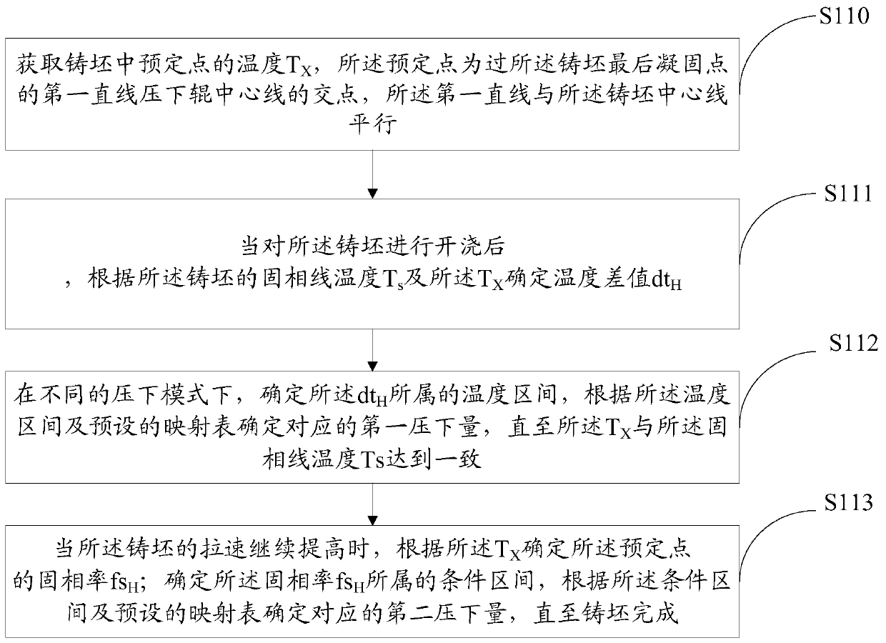
[0049] This embodiment provides a pressing method, such as figure 1 As shown, the methods include:

[0050] S110, obtaining the temperature T of a predetermined point in the slab X , the predetermined point is the intersection of the first straight line passing through the final solidification point of the slab and the centerline of the pressing roller, and the first straight line is parallel to the centerline of the slab;

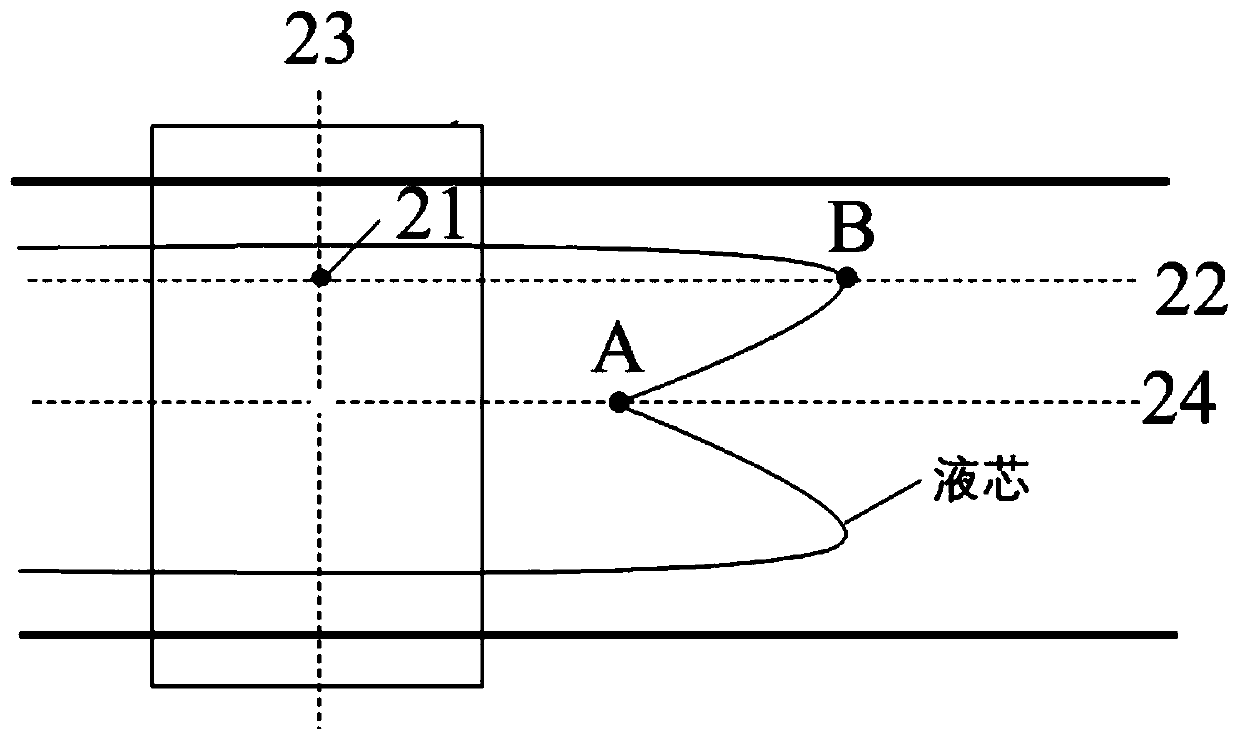
[0051] In the continuous casting process, the temperature T at a predetermined point in the slab is obtained X . Usually, the shape of the solidification front of the slab is irregular, and there is a certain distance between the first solidification point and the last solidification point, and they are distributed in a W shape, and the solidification morphology is as follows: figure 2 shown.

[0052] The first solidification point is generally at the center of the slab, such as figure 2 Mark A in , and the final freezing point is shown in Mark B. ...

Embodiment 2

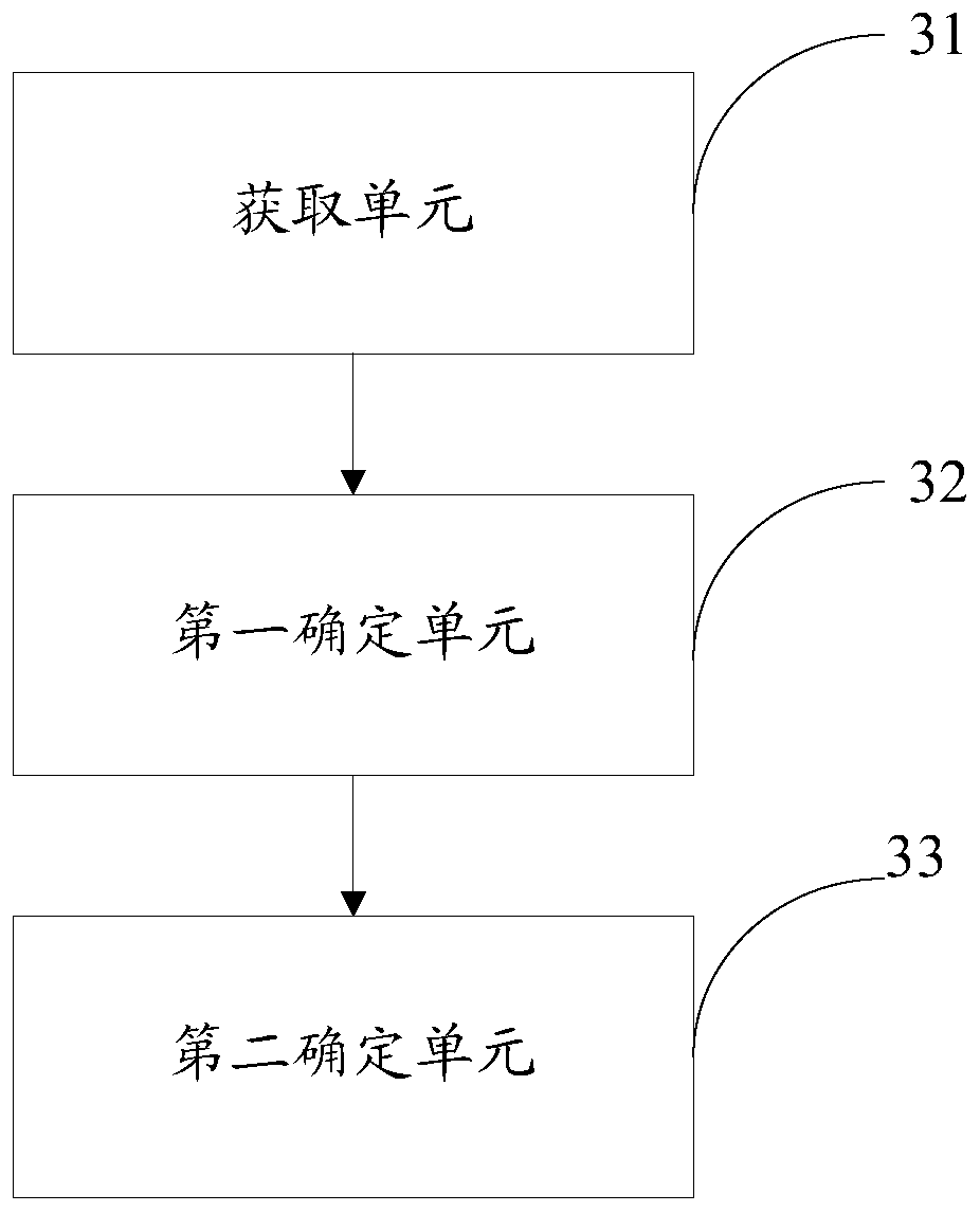
[0100] Corresponding to Embodiment 1, this embodiment also provides a pressing device, such as image 3 As shown, the device includes: an acquisition unit 31, a first determination unit 32 and a second determination unit 33;

[0101] The acquisition unit 31 is used to acquire the temperature T of a predetermined point in the slab X . Usually, the shape of the solidification front of the slab is irregular, and there is a certain distance between the first solidification point and the last solidification point, and they are distributed in a W shape, and the solidification morphology is as follows: figure 2 shown. The first solidification point is generally at the center of the slab, and the last solidification point is between the center and the surface of the slab.

[0102] exist figure 2 Among them, the predetermined point 21 is the intersection point of the first straight line 22 passing through the final solidification point of the slab and the centerline 23 of the pre...


PUM


Abstract

The embodiment of the invention provides a reduction method and device. The method includes the steps that the temperature TX of a predetermined point in a casting blank is obtained; the difference value dtH is determined according to the solidus temperature Ts and TX of the casting blank after casting of the casting blank; in different reduction modes, a temperature interval to which the dtH belongs is determined, and a corresponding first reduction amount is determined according to the temperature interval and a preset mapping table until the TX and the solidus temperature Ts are consistent;the mapping table is used for characterizing the corresponding relationship between the temperature interval and the first reduction amount, and the first reduction amount is 0 to 15 mm; when the drawing speed of the casting blank is continuously increased, the solid fraction fsH of the predetermined point is determined according to the TX; the condition interval to which the solid fraction fsH belongs is determined, a corresponding second reduction amount is determined according to the condition interval and the mapping table until the casting blank is completed; and the mapping table is also used for characterizing the corresponding relationship between the condition interval and the second reduction amount, and the second reduction amount is 0-20 mm.

Description

technical field [0001] The invention belongs to the technical field of continuous casting technology, and in particular relates to a pressing method and device. Background technique [0002] The core quality of continuous casting slabs has always troubled continuous casting workers, especially with the development of pipeline steel, acid-resistant container steel and high-grade marine steel, users have more and more requirements for the core quality of extra-thick slabs. high. [0003] In the prior art, the quality of the core of the slab is generally improved by light reduction technology, but the traditional light reduction method can only improve the center segregation phenomenon, but the problems of looseness and shrinkage holes in the core of the continuous casting slab have been solved. There is no improvement, so the core quality of the slab cannot be further improved. Contents of the invention [0004] Aiming at the problems existing in the prior art, the embodim...

Claims


Application Information

Patent Timeline
IPC IPC(8): B22D11/16
CPCB22D11/16
Inventor 赵新宇刘洋甄新刚赵晶王臻明王玉龙王俊吕延春邹扬秦丽晔张苏渊王海宝樊艳秋柴玉国
Owner SHOUGANG CORPORATION
Why Eureka
Try Eureka