PTFE layers and methods of manufacturing

a technology of ptfe layers and manufacturing methods, applied in the direction of prosthesis, transportation and packaging, blood vessels, etc., can solve the problems of largely unsatisfactory conventional ptfe layers, and achieve the effects of low porosity, no node, and low fluid permeability

Inactive Publication Date: 2006-10-19
TRIVASCULAR2
View PDF99 Cites 95 Cited by
  • Summary
  • Abstract
  • Description
  • Claims
  • Application Information

AI Technical Summary

Benefits of technology

[0007] Regarding layer embodiments, one layer embodiment is directed to a thin PTFE layer having low porosity, low fluid permeability, substantially no node and fibril structure, and having a thickness of about 0.00005 inch to about 0.005 inch. Another embodiment is directed to a thin PTFE layer, having substantially low porosity, substantially low fluid permeability, substantially no node and fibril structure, and a high degree of limpness and suppleness so to allow mechanical manipulation or strain of the PTFE layer without significant recoil or spring back.
[0012] In another embodiment, a thin PTFE layer has substantially low porosity, low fluid permeability, substantially no node and fibril structure, and a high degree of limpness and suppleness so to allow mechanical manipulation or strain of the PTFE layer without significant recoil or spring back. In another embodiment, a thin layer of PTFE includes a stretched layer of PTFE that has a closed cell microstructure with a plurality of interconnected high density regions substantially free of node and fibril microstructure between the high density regions. In another embodiment, a method of controlling the porosity, density or both of a PTFE layer, includes stretching the PTFE layer at least one time at a preselected temperature and preselected stretching agent content for the at least one stretch.

Problems solved by technology

As such, the conventional methods expand the PTFE layer and impart a porosity and permeability while only providing a negligible reduction in a thickness of the PTFE layer.
In situations where a thin PTFE layer, and specifically, a thin PTFE layer having a low fluid permeability is needed, conventional PTFE layers are largely unsatisfactory due to the porosity and highly permeable nature of the expanded PTFE layer.

Method used


Image

  • PTFE layers and methods of manufacturing
  • PTFE layers and methods of manufacturing
  • PTFE layers and methods of manufacturing

Examples


Embodiment Construction

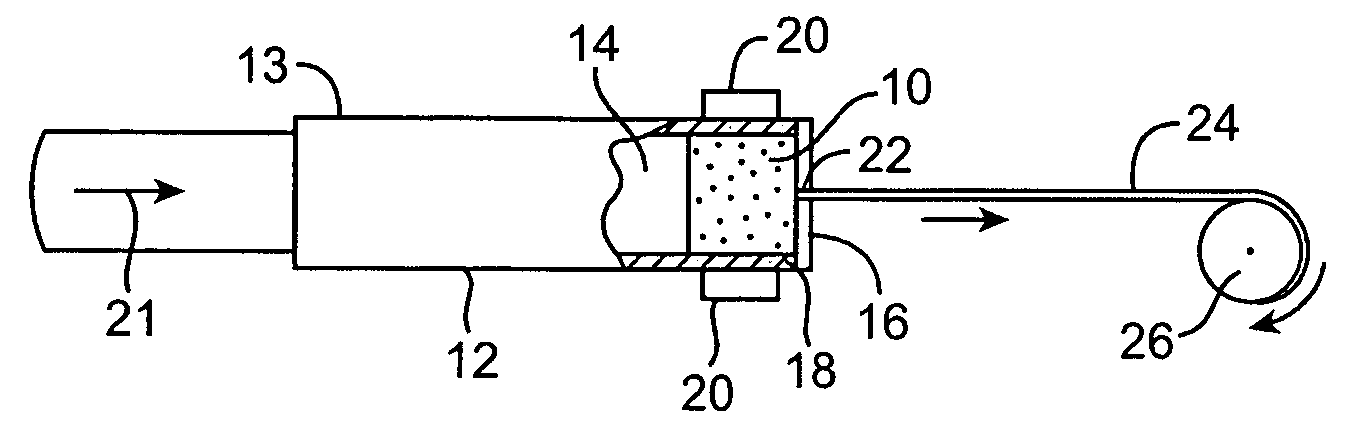
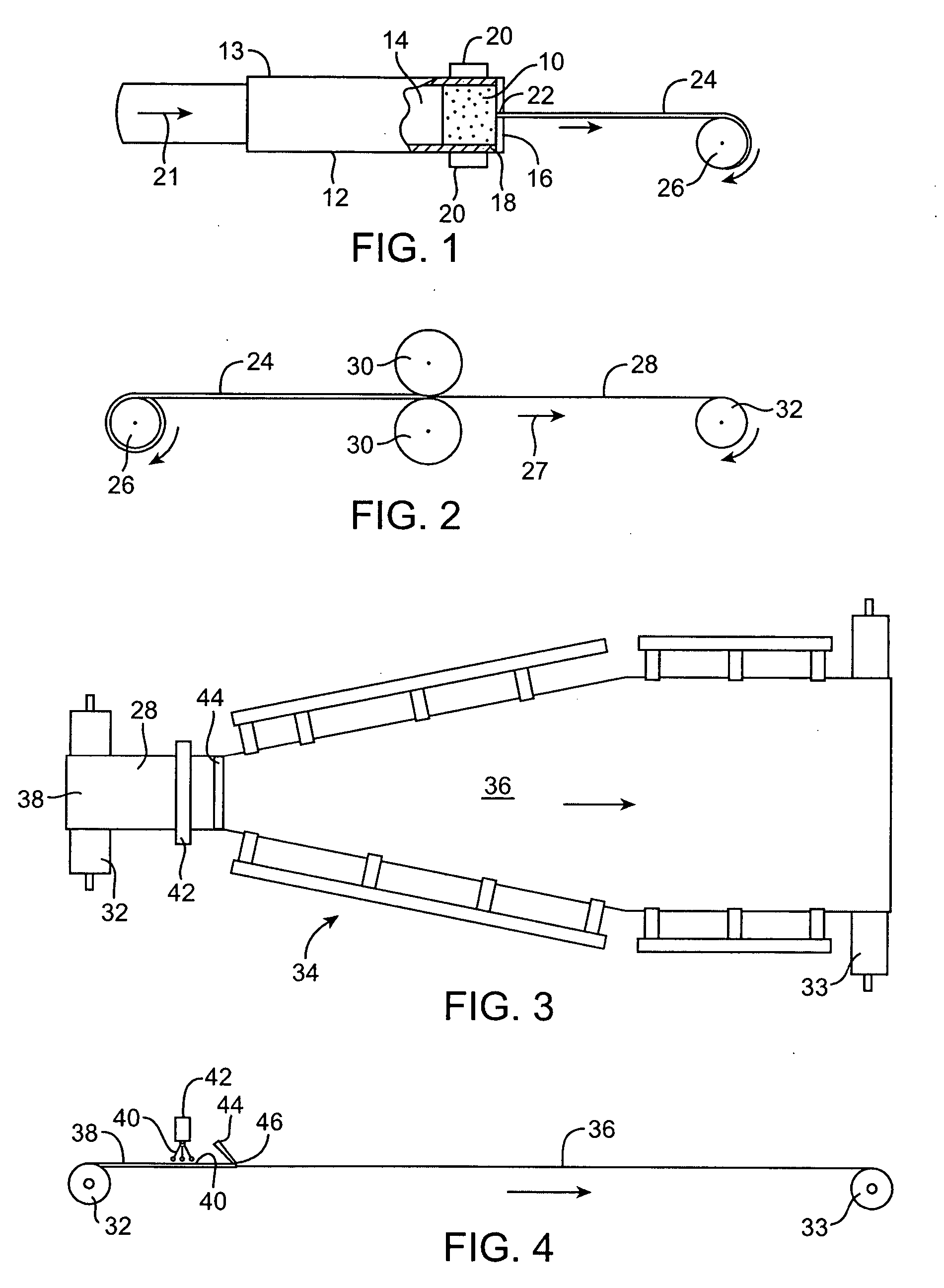
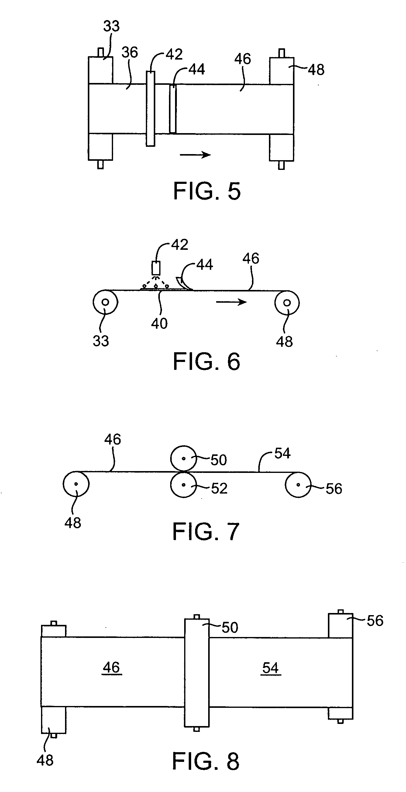
[0032] Embodiments of the present invention relate generally to thin PTFE layers, PTFE films, composite films having two or more PTFE layers and methods of manufacturing the PTFE layers, films and composite films. Some particular embodiments are directed to thin PTFE layers having low or substantially no fluid permeability with a microstructure that does not include significant fibril and nodal structure as is common with expanded PTFE layers. It may also be desirable for some embodiments of such thin PTFE layers that have a high degree of limpness and suppleness so to allow mechanical manipulation or strain of such a PTFE layer without significant recoil or spring back. Such PTFE layers may be manufactured and used for construction of endovascular grafts or other medical devices. For some applications, embodiments of PTFE films may include one or more discrete layers of PTFE that are secured together to form a composite film. As used herein, the term “composite film” generally refe...


PUM

PropertyMeasurementUnit
temperatureaaaaaaaaaa

Abstract

Thin PTFE layers are described having little or no node and fibril microstructure and methods of manufacturing PTFE layers are disclosed that allow for controllable permeability and porosity of the layers. In some embodiments, the PTFE layers may act as a barrier layer in an endovascular graft or other medical device.

Description

BACKGROUND OF THE INVENTION [0001] Polytetrafluoroethylene (PTFE) layers have been used for the manufacture of various types of intracorporeal devices, such as vascular grafts. Such vascular grafts may be used to replace, reinforce, or bypass a diseased or injured body lumen. One conventional method of manufacturing “expanded” PTFE layers is described in U.S. Pat. No. 3,953,566 by Gore. In the methods described therein, a PTFE paste is formed by combining a PTFE resin and a lubricant. The PTFE paste may be extruded. After the lubricant is removed from the extruded paste, the PTFE article is stretched to create a porous, high strength PTFE article. The expanded PTFE layer is characterized by a porous, open microstructure that has nodes interconnected by fibrils. [0002] Such an expansion process increases the volume of the PTFE layer by increasing the porosity, decreasing the density and increasing the internodal distance between adjacent nodes in the microstructure while not signific...

Claims


Application Information

Patent Timeline
Patent Type & Authority Applications(United States)
IPC IPC(8): B32B1/08A61F2/06B29C48/95
CPCA61F2/07Y10T428/1376A61F2250/0003A61L27/16A61L27/56B29C55/005B29K2027/18A61F2002/065Y10T428/1352A61F2/89A61F2002/075A61F2220/005B29C55/02Y10T428/139Y10T428/1393C08L27/18Y10T428/3154Y10T428/249981B29C48/08B29C48/0011B29C48/0018B29C48/022B29C48/95B29C55/08B29C48/94B29C43/24B29L2031/7532
Inventor HUMPHREY, JOSEPH W.SKIBA, JEFFREY B.
Owner TRIVASCULAR2
Why Eureka
Try Eureka