
Automatic screw mounting equipment

A technology of automatic installation and equipment, applied in metal processing equipment, metal processing, manufacturing tools, etc., can solve problems such as affecting mold processing efficiency, screw installation position deviation, difficult operation, etc., to ensure high efficiency, stability, and high-precision movement. Distance, easy to use effect

Pending Publication Date: 2019-11-22
东泰精密注塑(天津)有限公司
View PDF3 Cites 0 Cited by
  • Summary
  • Abstract
  • Description
  • Claims
  • Application Information

AI Technical Summary

Problems solved by technology

[0003] When processing the mold, it is often necessary to install screws on the mold. At present, there are many reports about automatic screw installation equipment. The patent of CN105035675B discloses an automatic production line for screw installation. The conveying device and the screw installation jig realize the automatic nailing of the heat-adjustable screws in the circuit breaker housing, which reduces the labor intensity of the workers and improves the safety of the workers at work. When the accuracy is poor, it is easy to cause the deviation of the screw installation position
[0004] The patent of CN103157987A discloses a kind of screw automatic installation equipment, this equipment has good versatility, can be adjusted flexibly along with the renewal of the product, can use the screw of different models and specifications, prevent the screw from being missed, and can be used for one or more days The screws required by the output are put into the screw supply machine at one time, without filling a single quantity, the operation is simple, and the inspection is convenient. The use of the touch screen greatly increases the operability of the equipment and ensures the good quality of the product in the screwing process. It can also be used for other work, and the screwdriver part can be refitted into other structures to realize functions such as grinding, dispensing, pasting, and code scanning. However, researchers have found that the device is less efficient in controlling and has different Stability, affecting the processing efficiency of the mold
[0005] The patent of CN110076555A discloses an electric screwdriver and screw installation equipment for automatically introducing screws. By setting the guide piece, the screw can be clamped between the clamping pieces through the guide tube through the guide hole, so that the electric screwdriver can pass through the guide. The material hole is in contact with the screw and when the screw is aligned with the installation position, the electric screwdriver squeezes the screw, and the screw pushes away the clamping part of the clamping part and is tightened on the installation position of the workpiece. However, after research The personnel found that the structure of the device is relatively complicated, the operation is not easy to learn, and the operation is difficult

Method used


Image

  • Automatic screw mounting equipment
  • Automatic screw mounting equipment
  • Automatic screw mounting equipment

Examples


Embodiment 1

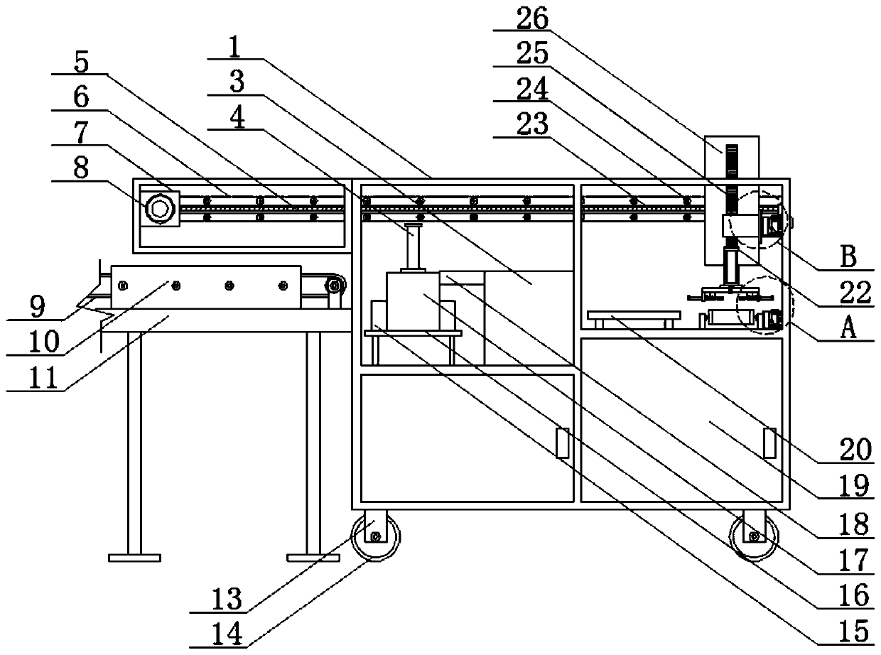
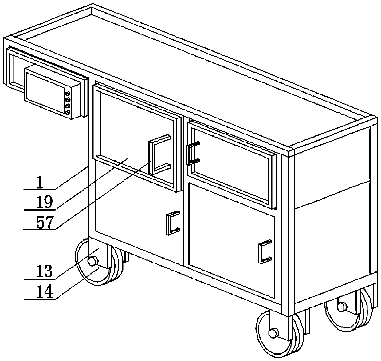
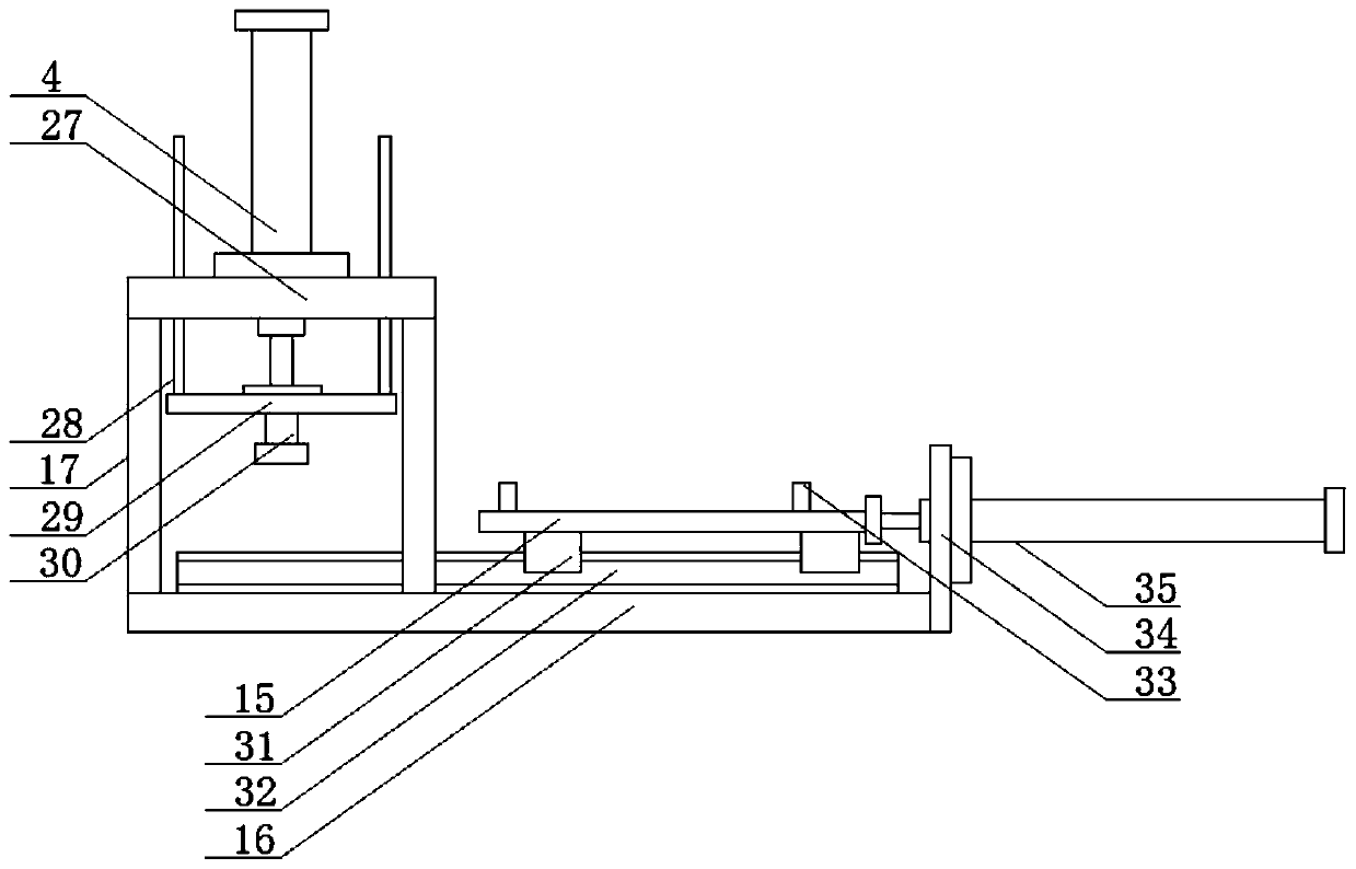
[0035] refer to figure 1 , 2 , 3, 4, 5, 6, 7, 8, a screw automatic installation device, including a shell 1, which plays a protective role, and the opposite side walls in the shell 1 are jointly fixed with partitions, and the partitions will The housing 1 is divided into a cavity and a placement cavity, which is convenient for partition placement. A mounting plate 6 is detachably connected to the side wall at one end of the cavity by more than two screws 24. One side of the mounting plate 6 is provided with a first chute 23, the first chute 23 is provided with an adjustment device, the adjustment device is provided with a fixed box 26, the movement of the adjustment device drives the fixed box 26 to move, the fixed box 26 is provided with a lifting device, the lifting device is provided with a rack 25, fixed One side of the box 26 is provided with a rotating device, the rotating device and the rack 25 are connected to each other, and the rotating device rotates to drive the r...

Embodiment 2

[0049] refer to figure 1 , 2 , 3, 4, 5, 6, 7, 8, a screw automatic installation device, including a shell 1, which plays a protective role, and the opposite side walls in the shell 1 are jointly fixed with partitions, and the partitions will The housing 1 is divided into a cavity and a placement cavity, which is convenient for partition placement. A mounting plate 6 is detachably connected to the side wall at one end of the cavity by more than two screws 24. One side of the mounting plate 6 is provided with a first chute 23, the first chute 23 is provided with an adjustment device, the adjustment device is provided with a fixed box 26, the movement of the adjustment device drives the fixed box 26 to move, the fixed box 26 is provided with a lifting device, the lifting device is provided with a rack 25, fixed One side of box 26 is provided with rotating device, and rotating device is connected with tooth bar 25, and rotating device rotates and drives tooth bar 25 to move, and ...

Embodiment 3

[0064] refer to figure 1 , 2 , 3, 4, 5, 6, 7, 8, a screw automatic installation device, including a shell 1, which plays a protective role, and the opposite side walls in the shell 1 are jointly fixed with partitions, and the partitions will The housing 1 is divided into a cavity and a placement cavity, which is convenient for partition placement. A mounting plate 6 is detachably connected to the side wall at one end of the cavity by more than two screws 24. One side of the mounting plate 6 is provided with a first chute 23, the first chute 23 is provided with an adjustment device, the adjustment device is provided with a fixed box 26, the movement of the adjustment device drives the fixed box 26 to move, the fixed box 26 is provided with a lifting device, the lifting device is provided with a rack 25, fixed One side of the box 26 is provided with a rotating device, the rotating device and the rack 25 are connected to each other, and the rotating device rotates to drive the r...


PUM


Abstract

The invention discloses automatic screw mounting equipment which comprises a shell. A partition plates is jointly fixed between opposite side walls in the shell, the partition plates divide the shellinto a cavity and a placing cavity, one end side wall in the cavity is detachably connected with a mounting plate through two or more screws, one side of the mounting plate is provided with a first sliding groove, an adjusting device is arranged in the first sliding groove, and a fixing box is arranged on the adjusting device. A lifting device is arranged in the fixing box, a rack is arranged on the lifting device, and a rotating device is arranged on one side of the fixing box. The problem of poor precision in screw mounting is solved, influences caused by unqualified mounting on mold qualityare avoided, the problem of large operation difficulty is solved, the operation difficulty is lowered in a graphical operation way, grasping is easy, high efficiency and stability of system operationare ensured, mold machining efficiency is improved, the labor intensity is lowered, time and labor are saved, and the cost is saved.

Description

technical field [0001] The invention relates to the technical field of screw installation, in particular to an automatic screw installation device. Background technique [0002] Screw refers to a screw, which is a tool that uses the physical and mathematical principles of the oblique circular rotation and friction of the object to tighten the device parts step by step. The screw is a common fastener used in machinery, electrical appliances and buildings. widely used. The general material is metal or plastic, and it is cylindrical in shape, and the concave-convex grooves engraved on the surface are called threads. [0003] When processing the mold, it is often necessary to install screws on the mold. At present, there are many reports about automatic screw installation equipment. The patent of CN105035675B discloses an automatic production line for screw installation. The conveying device and the screw installation jig realize the automatic nailing of the heat-adjustable sc...

Claims


Application Information

Patent Timeline
Patent Type & Authority Applications(China)
IPC IPC(8): B23P19/06B23P19/00
CPCB23P19/06B23P19/00B23P19/001
Inventor 张洪国张婷婷王格蒋海萍刘丽娜周宇张斌轩程春山张磊王凯章勇高红远付扬程春福张保良祁辉
Owner 东泰精密注塑(天津)有限公司
Learn More