
an injection mold

A technology for injection molds and templates, which is applied in the field of injection molds, and can solve problems such as insufficient product strength, product appearance deformation, and thick round plastic columns that are not easy to cool.

Active Publication Date: 2022-02-11
友信精密实业(深圳)有限公司
View PDF5 Cites 0 Cited by
  • Summary
  • Abstract
  • Description
  • Claims
  • Application Information

AI Technical Summary

Problems solved by technology

[0004] The purpose of the present invention is to provide an injection mold to solve the problem of insufficient product strength and deformation of the product appearance due to the thick round rubber column being too thick and difficult to cool when the existing injection mold produces products composed of square plates and thick round rubber columns. question

Method used


Image

  • an injection mold
  • an injection mold
  • an injection mold

Examples


Embodiment Construction

[0027] In order to facilitate the understanding of the present invention, the present invention will be described more fully below with reference to the associated drawings. Several embodiments of the invention are shown in the drawings. However, the present invention can be embodied in many different forms and is not limited to the embodiments described herein. Rather, these embodiments are provided so that the disclosure of the present invention will be thorough and complete.

[0028] It should be noted that when an element is referred to as being “fixed on” another element, it may be directly on the other element or there may be an intervening element. When an element is referred to as being "connected to" another element, it can be directly connected to the other element or intervening elements may also be present. The terms "left", "right" and similar expressions are used herein for the purpose of illustration only.

[0029] Unless otherwise defined, all technical and ...


PUM


Abstract

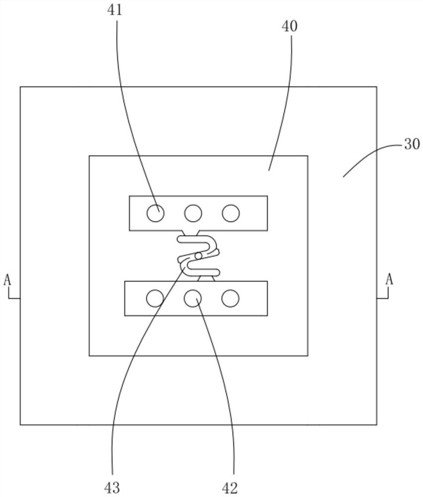
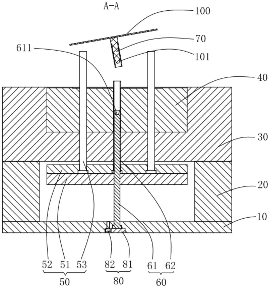
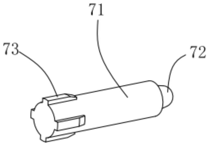
The invention provides an injection mold, which comprises a lower template, a square iron, a lower mold core, a rear mold core, an ejector assembly, a push assembly and an elastic part. A plate cavity is formed at the upper end of the rear mold core, and the middle part of the rear mold core Each is provided with a cavity hole, and the pushing assembly includes a push tube inner needle and a push tube, and the elastic part includes a cylinder, a guide head arranged at one end of the cylinder, and a plurality of side edges arranged at the other end of the cylinder. The rib is positioned, and the guide head fits with the end of the needle in the push tube. When processing the above-mentioned injection mold, snap the guide head of the elastic part into the end of the needle in the push tube, and make the positioning rib abut against the inner wall of the push tube, so that the cylinder is located at the center of the push tube, close the mold and inject plastic, so that the plastic A square plate is formed in the plate cavity, and a thick round rubber column is formed in the push tube in the cavity hole. Among them, the plastic-wrapped elastic parts form a thick round rubber column, so that there is no need for heat dissipation inside the thick round rubber column, which solves the problem of insufficient product strength. , The problem of product appearance deformation.

Description

technical field [0001] The invention relates to the technical field of injection molding, in particular to an injection mold. Background technique [0002] In injection molding products, there is a structural product, which includes square plates and thick round rubber columns. The basic wall thickness of square plates is T. When processing, the product requires good front appearance and no basic defects. Among them, thick round rubber The diameter of the column is multiple times of T, the thick round plastic column is set at the root of the connection of the outer surface of the square plate, and the thick column is solid. [0003] The difficulty in processing this type of structural product is that the rubber at the root of the thick round rubber column is too thick. After the melt fills the mold cavity, the heat is concentrated and it is not easy to cool down; It takes a long time to cool, and there are serious shrinkage pit defects on the appearance of the thick round r...

Claims


Application Information

Patent Timeline
Patent Type & Authority Patents(China)
IPC IPC(8): B29C45/26B29C45/27B29C45/40
CPCB29C45/26B29C45/2602B29C45/27B29C45/4005
Inventor 章庆华
Owner 友信精密实业(深圳)有限公司
Learn More