Oxygen conveying pipeline for sewage treatment aeration device

An aeration device and sewage treatment technology, applied in water/sewage treatment, water/sewage treatment equipment, water aeration, etc., can solve the problems of concentrated oxygen transportation, easy blockage of openings on pipes, low utilization rate, etc. Small possibility, the effect of improving oxygen utilization rate and expanding the delivery range

Inactive Publication Date: 2019-11-22
张具琴
View PDF0 Cites 2 Cited by
  • Summary
  • Abstract
  • Description
  • Claims
  • Application Information

AI Technical Summary

Problems solved by technology

[0004] In view of the above situation, in order to overcome the defects of the prior art, the present invention provides an oxygen delivery pipe for the aeration device of sewage treatment, which solves the problem of low utilization rate caused by concentrated oxygen delivery and easy blockage of the opening on the pipeline

Method used


Image

  • Oxygen conveying pipeline for sewage treatment aeration device
  • Oxygen conveying pipeline for sewage treatment aeration device
  • Oxygen conveying pipeline for sewage treatment aeration device

Examples


Embodiment 1

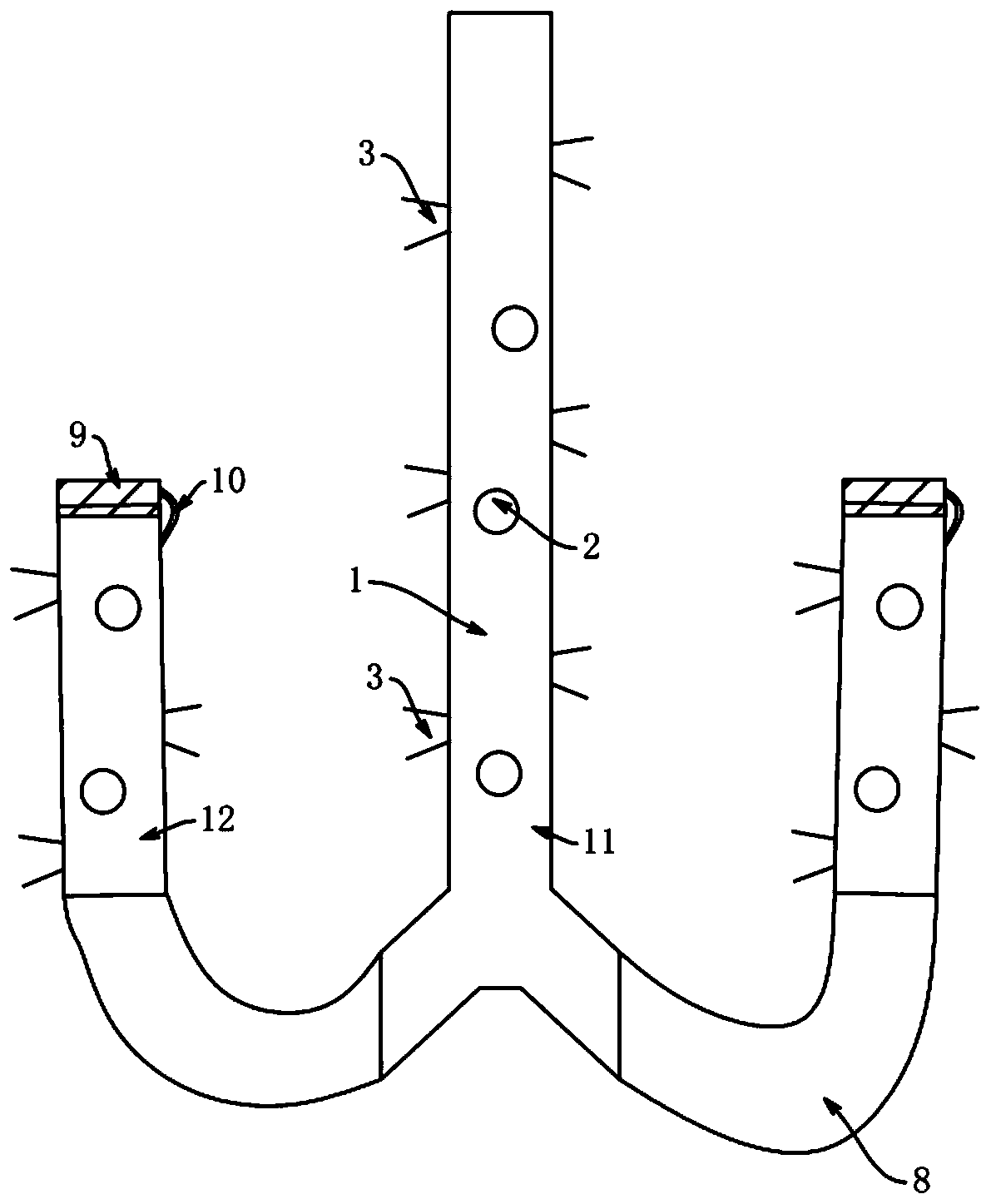
[0017] Embodiment one: by Figure 1 to Figure 4 It is given that the oxygen delivery pipe used for the aeration device for sewage treatment includes a pipeline 1 for transporting oxygen. The surface of the pipeline 1 is provided with a plurality of ventilation holes 2, and the gas enters from the opening above the pipeline 1 and passes through each ventilation hole. 2 and the opening below the pipeline 1 enters the liquid and fully contacts with the liquid to improve the utilization rate of oxygen. Each of the vent holes 2 is provided with a connector 3 for communicating the inside of the pipeline 1 with the external liquid, and each of the connectors 3 is in the shape of a circular platform, and the connecting head 3 is made of rubber material. The outer surface of the smaller end face of each connecting head 3 is provided with a sealing gasket and is detachably connected to the air hole 2 through the sealing gasket. The connecting head 3. The diameter of the circle at the sm...

Embodiment 2

[0020] Embodiment 2: In one embodiment, the pipeline 1 includes a main pipe 11 and a plurality of branch pipes 12, the diameter of each branch pipe 12 is consistent with the diameter of the main pipe 11, and the length of the branch pipe 12 is 1 / 2 of the length of the main pipe 11, so The bottom of the main pipe 11 is provided with a plurality of branch ports, the branch ports are in one-to-one correspondence with the branch pipes 12 and are flexibly connected through the U-shaped hose 8, and the branch pipes 12 connected to the branch ports at the bottom of the main pipe 11 Turning, the gas in the branch pipe 12 enters from the bottom of the branch pipe, and is discharged from the opening above the branch pipe 12 and the vent holes provided on the outer wall. The two ends of the U-shaped hose 8 are internally provided with gaskets, and the gaskets and The inner wall of the U-shaped hose 8 is glued, and the surface of the sealing pad is provided with oblique strip-shaped anti-s...


PUM

PropertyMeasurementUnit
thicknessaaaaaaaaaa
thicknessaaaaaaaaaa
diameteraaaaaaaaaa

Abstract

The invention relates to the technical field of water purification equipment and especially relates to an oxygen conveying pipeline, in particular to an oxygen conveying pipeline for a sewage treatment aerator. In the prior art, oxygen conveying is concentrated, so that the utilization rate is low, and a pipeline is liable to be blocked if a vent hole is formed in the pipeline. In the invention, the oxygen conveying pipeline for a sewage treatment aeration device includes a duct, wherein a plurality of vent holes are formed in the surface of the pipeline; a connector is arranged on each vent hole; each connector is in a circular truncated cone shape. The smaller end of the end surface of each connector is connected with the vent hole, while a filter screen is arranged at the larger end ofthe end face of each connector; a U-shaped filter tip is arranged outside each filter screen, the U-shaped filter tips are made of rubber materials, and protrusions formed by combining a plurality ofvalves are arranged at openings of the U-shaped filter tips The oxygen conveying pipeline can increase oxygen utilization rate, and good development prospects are achieved in the technical field of water purification equipment.

Description

technical field [0001] The invention relates to the technical field of water purification equipment, in particular to an oxygen delivery pipe used in an aeration device for sewage treatment. Background technique [0002] In the process of cleaning the sewage, it is necessary to artificially inject air into the biochemical aeration tank through the equipment, so that the liquid in the tank is in contact with the air and oxygenated. The contact surface between oxygen and liquid directly affects the utilization rate of oxygen. The existing aeration device The channel is usually connected by a blower, the air is introduced into the liquid, and the flow speed of the liquid is accelerated by agitation, thereby improving the utilization rate of oxygen. [0003] Directly passing air into the liquid will cause the gas to be too concentrated, and the stirring range will be too large to cause a part of the gas to escape directly without reacting with the liquid, and the oxygen utilizat...

Claims


Application Information

Patent Timeline
Patent Type & Authority Applications(China)
IPC IPC(8): C02F7/00C02F3/02
CPCC02F3/02C02F7/00C02F2201/002Y02W10/10
Inventor 张具琴
Owner 张具琴
Why Eureka
Try Eureka