Structure and method for monitoring hydraulic tunnel dynamic water pressure based on velocity head correction

A technology of flow rate head and hydraulic tunnel, which is applied in hydraulic engineering, measurement of fluid pressure, simultaneous measurement of multiple hydraulic valves, etc. It can solve the deviation of tunnel operation management guidance, cannot reflect the tunnel hydraulic load, and cannot reflect the system flow rate and head, etc. problem, to achieve the effect of facilitating promotion and application, uploading in real time, and improving monitoring accuracy

Active Publication Date: 2019-11-22
NANJING AUTOMATION INST OF WATER CONSERVANCY & HYDROLOGY MINIST OF WATER RESOURCES +4
View PDF7 Cites 5 Cited by
  • Summary
  • Abstract
  • Description
  • Claims
  • Application Information

AI Technical Summary

Problems solved by technology

The existing water pressure monitoring equipment is mainly a piezometer, and its monitoring results can only reflect the position head and pressure head, but cannot reflect the flow rate head of the system
The lack of flow rate head in the total water head of the system will not be able to reflect the real hydraulic load during the operation of the tunnel, and the monitoring results will also have deviations in the guidance of tunnel operation management

Method used


Image

  • Structure and method for monitoring hydraulic tunnel dynamic water pressure based on velocity head correction
  • Structure and method for monitoring hydraulic tunnel dynamic water pressure based on velocity head correction
  • Structure and method for monitoring hydraulic tunnel dynamic water pressure based on velocity head correction

Examples


Embodiment Construction

[0046] The technical solutions provided by the present invention will be described in detail below in conjunction with specific examples. It should be understood that the following specific embodiments are only used to illustrate the present invention and are not intended to limit the scope of the present invention.

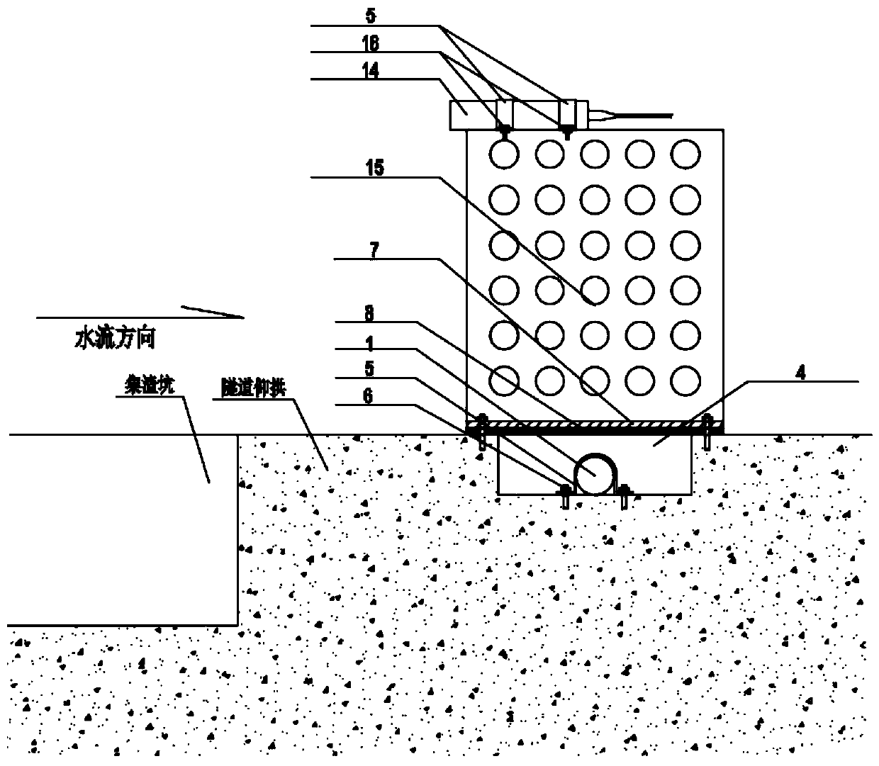
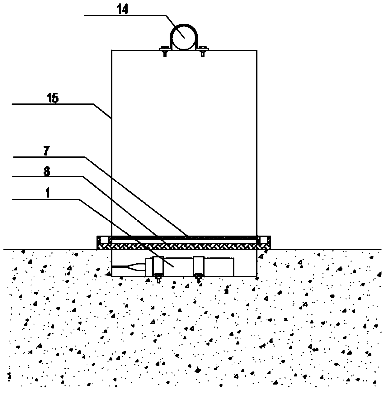
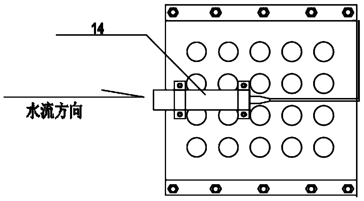
[0047] Such as figure 1 , figure 2 As shown, the hydraulic tunnel dynamic water pressure monitoring structure based on flow rate and head correction provided by the present invention includes a hydrostatic pressure sensor 1, a total water pressure sensor 14, a high-speed fiber grating demodulator 2, a hydrostatic pressure sensor 1 and a total water pressure sensor 14 are respectively connected to the high-speed fiber grating demodulator through the fiber pigtail cable 3. The hydrostatic pressure sensor 1 is installed in the tunnel cavity 4, such as figure 2 , image 3 , Figure 4 As shown, the hydrostatic pressure sensor 1 is fixed at the bottom of the cavi...


PUM


Abstract

The invention provides a structure and method for monitoring hydraulic tunnel dynamic water pressure based on velocity head correction. The structure comprises a hydrostatic pressure sensor, a total water pressure sensor and a high-speed fiber bragg grating demodulator, and the hydrostatic pressure sensor and the total water pressure sensor are connected with the high-speed fiber bragg grating demodulator through optical fiber stern lines respectively; the hydrostatic pressure sensor is mounted in a cavity of a tunnel, and the mounting direction is perpendicular to the direction of water flow,the hydrostatic pressure sensor is fixed to the bottom of the cavity through clamps and fasteners, and geotechnical cloth and a mesh steel cover are arranged at the top of the cavity from the insideto the outside; and the total water pressure sensor is mounted on a support and located above the hydrostatic pressure sensor, and a total water pressure sensor permeable stone faces the direction ofthe upstream of the water flow. According to the structure and method for monitoring the hydraulic tunnel dynamic water pressure based on the velocity head correction, two FBG water pressure sensors arranged in different orientations and at different heights are used for performing velocity head correction on a total water head, the influences of factors such as a boundary layer and flat plate turbulence are eliminated, and the monitoring accuracy of the sensor is improved.

Description

technical field [0001] The invention belongs to the technical field of hydraulic engineering safety monitoring, and relates to a dynamic water pressure monitoring structure and method of hydraulic tunnels based on flow rate and head correction. Background technique [0002] At present, a large number of hydraulic tunnels have been built in China. As tunnel construction develops towards long distances, large buried depths, and high water heads, the structural safety monitoring of tunnels is becoming more important. The internal water pressure is one of the important loads on the tunnel structure during the operation period of the tunnel, especially the pipeline water hammer caused by the operation of gates and pump valves during the operation of the tunnel, which is the most common phenomenon of tunnel damage. Since water hammer is a reciprocating and alternating periodic change in which the water pressure in the tunnel pipeline rises and falls sharply, continuous high-freque...

Claims


Application Information

Patent Timeline
Patent Type & Authority Applications(China)
IPC IPC(8): E02B9/00E02B9/06G01L11/02G01L15/00
CPCE02B9/00E02B9/06G01L11/025G01L15/00Y02E10/20
Inventor 张俊杰李代茂黄建明杨建喜黄井武王建学周克明徐海峰徐兰玉李家群李东
Owner NANJING AUTOMATION INST OF WATER CONSERVANCY & HYDROLOGY MINIST OF WATER RESOURCES
Why Eureka
Try Eureka