
Garment dryer for textile production

A drying machine and garment technology, applied in the field of textile production, can solve the problems of reducing drying efficiency, increasing energy consumption, polluting the environment, etc., and achieving the effects of increasing the range, increasing drying efficiency, and uniform heat.

Active Publication Date: 2019-11-22
泰州市海鑫机电制造有限公司
View PDF5 Cites 8 Cited by
  • Summary
  • Abstract
  • Description
  • Claims
  • Application Information

AI Technical Summary

Problems solved by technology

[0003] The existing garment drying equipment for garment production produces peculiar smell during the production process, seriously pollutes the environment, and is not conducive to the sustainable development of production; at the same time, the drying of garments is not comprehensive, which seriously affects the production efficiency. drive, to drive the clothes to rotate, so as to achieve the purpose of drying evenly, but the use of the drive motor increases the loss of energy, which violates the general direction of energy saving, and the existing dryer does not have a shaking function, and if there is something on the clothes, it can fall When there are water droplets, the drying efficiency will be greatly reduced

Method used


Image

  • Garment dryer for textile production
  • Garment dryer for textile production
  • Garment dryer for textile production

Examples


Embodiment 1

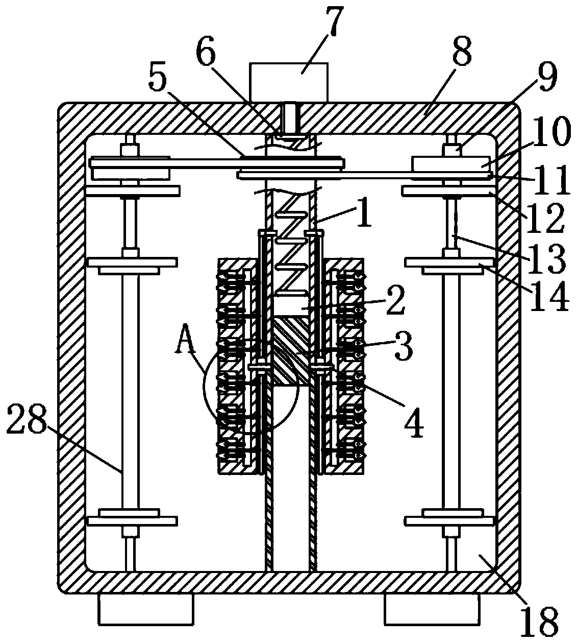
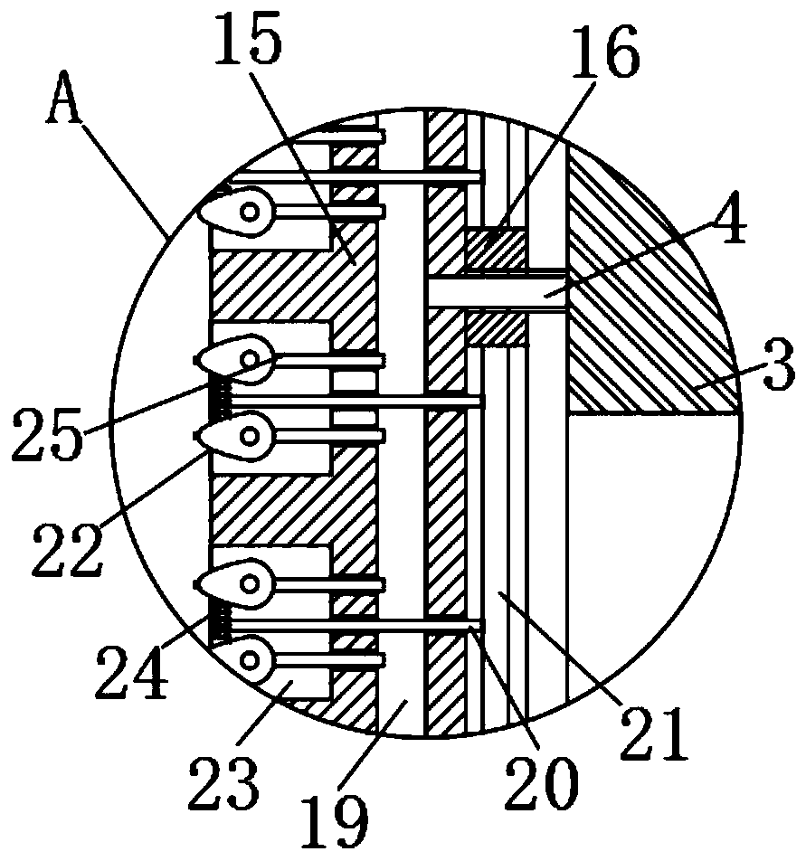
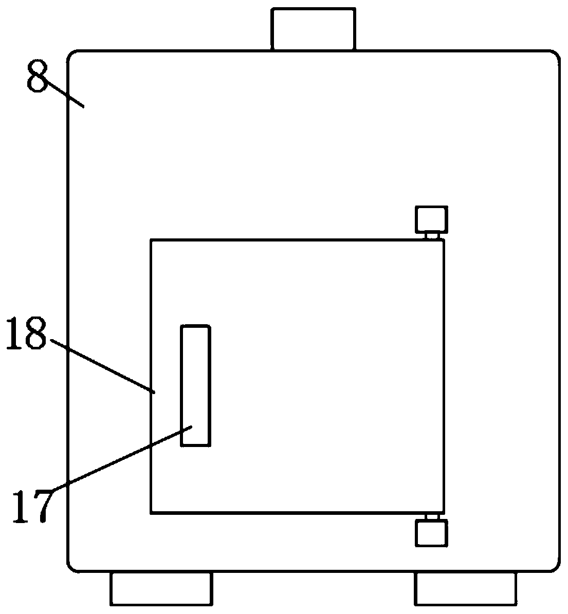
[0023] refer to Figure 1-3 , a garment dryer for textile production, comprising a drying box 8, the drying box 8 is provided with a casing 1 vertically rotatably connected to the inner wall of the drying box 8, and a piston is arranged in the upper half of the casing 1 2. The upper end of the piston 2 is elastically connected to the inner top of the sleeve 1 through the first spring 6, the lower end of the piston 2 is fixedly connected with the threaded block 3, and the inner wall of the lower half of the sleeve 1 is provided with a thread that matches the threaded block 3 Two connecting blocks 16 are fixedly connected symmetrically to both sides of the sleeve pipe 1, and the opposite sides of the two connecting blocks 16 are fixedly connected with a device bar 15, and the device bar 15 is provided with an air chamber 19, and one part of the device bar 15 A plurality of square grooves 23 are arranged at equal intervals on the side, and two nozzles 22 are rotatably connected i...

Embodiment 2

[0027] refer to Figure 4-6, the difference between this embodiment and Embodiment 1 is that the relative inner walls of the drying box 8 are fixedly connected with the installation plate 12, the side wall of the first sleeve 9 runs through the installation plate 12, and the inner wall of the second sleeve 28 Fixedly connected with slide bar 27, rotating bar 13 is provided with the chute 26 that matches with slide bar 27, and rotating bar 13 is positioned at mounting plate 12 and clothes hanger 14 and is partially sleeved with so that the first sleeve 9 and the second The second spring 31 elastically connected to the sleeve 28, the upper end of the clothes hanger 14 is fixedly connected with two round head rods 29, and the lower end of the mounting plate 12 is fixedly connected with a plurality of hemispherical blocks matched with the round head rods 29. 30.

[0028] In this embodiment, when there are dripping water droplets on the clothes to be dried, the drying efficiency o...


PUM


Abstract

The invention discloses a garment dryer for textile production. The garment dryer comprises a drying case, wherein the drying case is internally provided with a casing pipe which is vertically and rotationally connected with the inner wall of the drying case; a piston is arranged in the upper-half part of the casing pipe; the upper end of the piston is elastically connected with the inner top of the casing pipe through a spring; a thread block is fixedly connected to the lower end of the piston; a thread wall matched with the thread block is arranged on the inner wall of the lower-half part ofthe casing pipe; two connecting blocks are symmetrically and fixedly connected to two sides of the casing pipe; device strips are fixedly connected to the sides, which are away from each other, of the two connecting blocks separately and are internally provided with wind cavities; certain sides of the device strips are equidistantly provided with a plurality of square grooves; and two spray headsare rotationally connected with the inner part of each square groove. The dryer can improve the drying efficiency; in addition, without use of a drive motor, the use of energy is increased.

Description

technical field [0001] The invention relates to the field of textile production, in particular to a garment dryer for textile production. Background technique [0002] Natural drying is seriously affected by the weather. Normal clothing factory equipment is equipped with dryers, which can quickly dry. The dryer uses a heat source to heat the air, turning the air into dry hot air, and making it continuously in contact with the clothing containing moisture, so that the moisture on the fabric is gradually evaporated to achieve the purpose of rapid drying. [0003] The existing garment drying equipment for garment production produces peculiar smell during the production process, seriously pollutes the environment, and is not conducive to the sustainable development of production; at the same time, the drying of garments is not comprehensive, which seriously affects the production efficiency. drive, to drive the clothes to rotate, so as to achieve the purpose of drying evenly, b...

Claims


Application Information

Patent Timeline
Patent Type & Authority Applications(China)
IPC IPC(8): F26B15/08F26B21/00F26B5/00F26B25/02
CPCF26B5/00F26B15/08F26B21/004F26B25/02
Inventor 于妍
Owner 泰州市海鑫机电制造有限公司
Learn More