
Laser target reporting system

A laser target and laser technology, applied in the field of shooting training systems, can solve the problems of high manufacturing and maintenance costs of a photoelectric sensing type automatic target reporting system, high cost of an electrode embedded type target reporting system, and high manufacturing costs, and achieve a simple structure. , The effect of safe and convenient use and low manufacturing cost

Pending Publication Date: 2019-11-22
南京拓恒无人系统研究院有限公司
View PDF5 Cites 0 Cited by
  • Summary
  • Abstract
  • Description
  • Claims
  • Application Information

AI Technical Summary

Problems solved by technology

[0003] The present invention provides a laser target reporting system, which can effectively solve the existing target reporting technology proposed in the above-mentioned background technology, including electrode embedding, photoelectric sensing, image processing and acoustic-electric positioning. The method of judging the target is one-time, and the target body will be scrapped after each shooting, which leads to the high cost of the electrode-embedded target reporting system, the high manufacturing and maintenance costs of the photoelectric sensor automatic target reporting system, and the image processing. The manufacturing cost of the automatic target reporting system is high, the calculation is relatively complicated and the amount of calculation is large, and it needs professional operation. The acoustic and electric positioning automatic target reporting system requires professional operation and is relatively complicated.

Method used


Image

  • Laser target reporting system
  • Laser target reporting system
  • Laser target reporting system

Examples


Embodiment 1

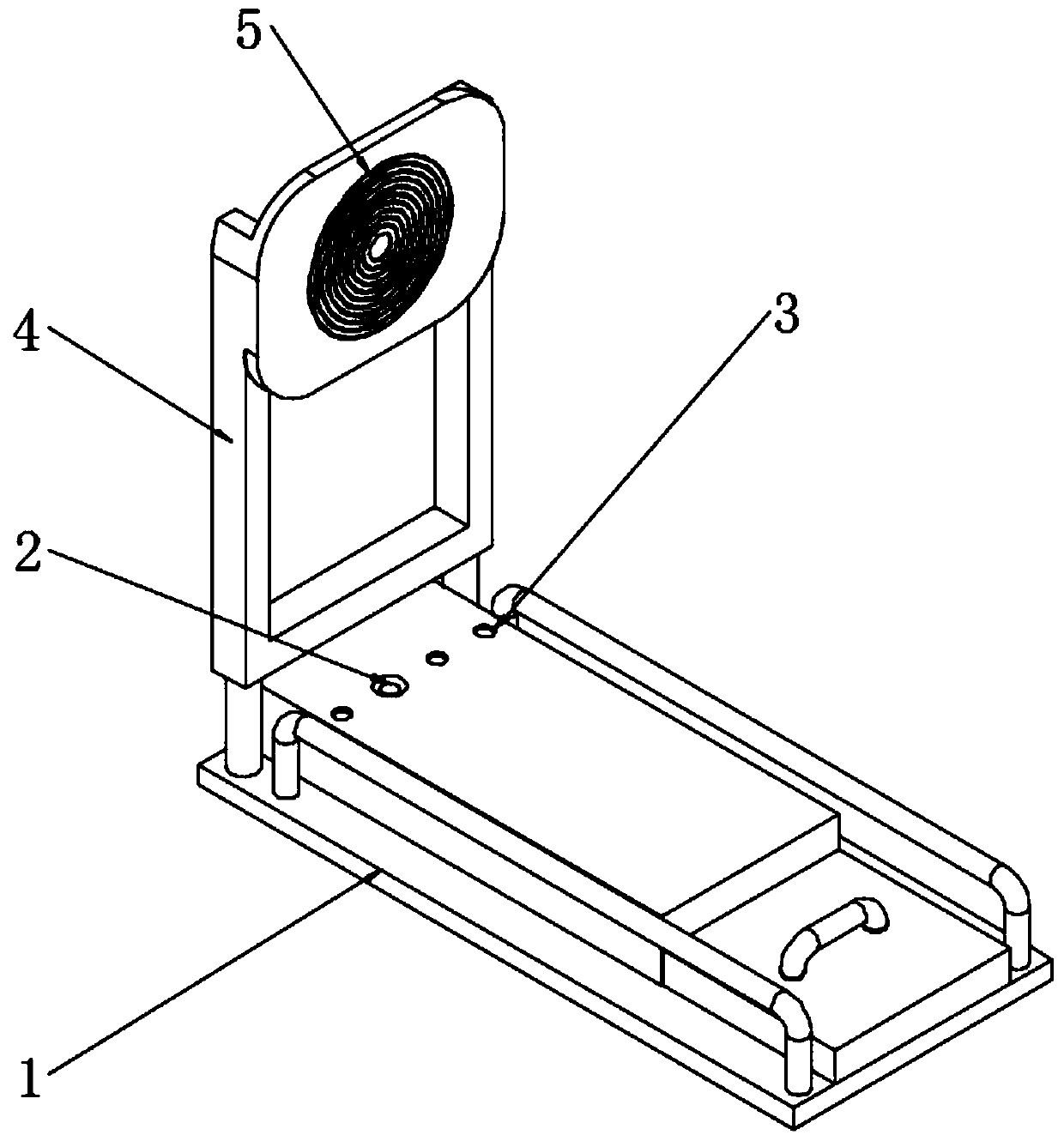
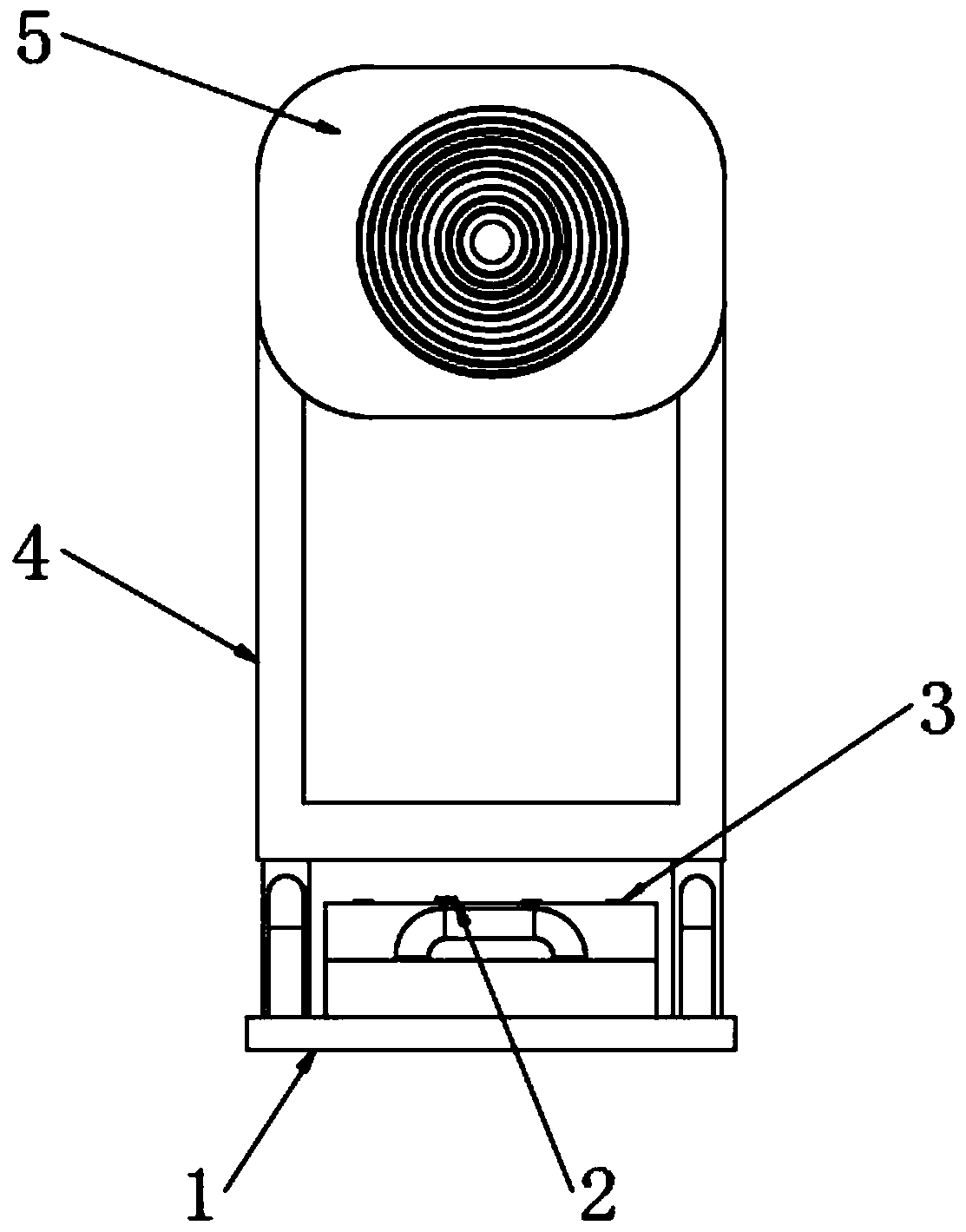
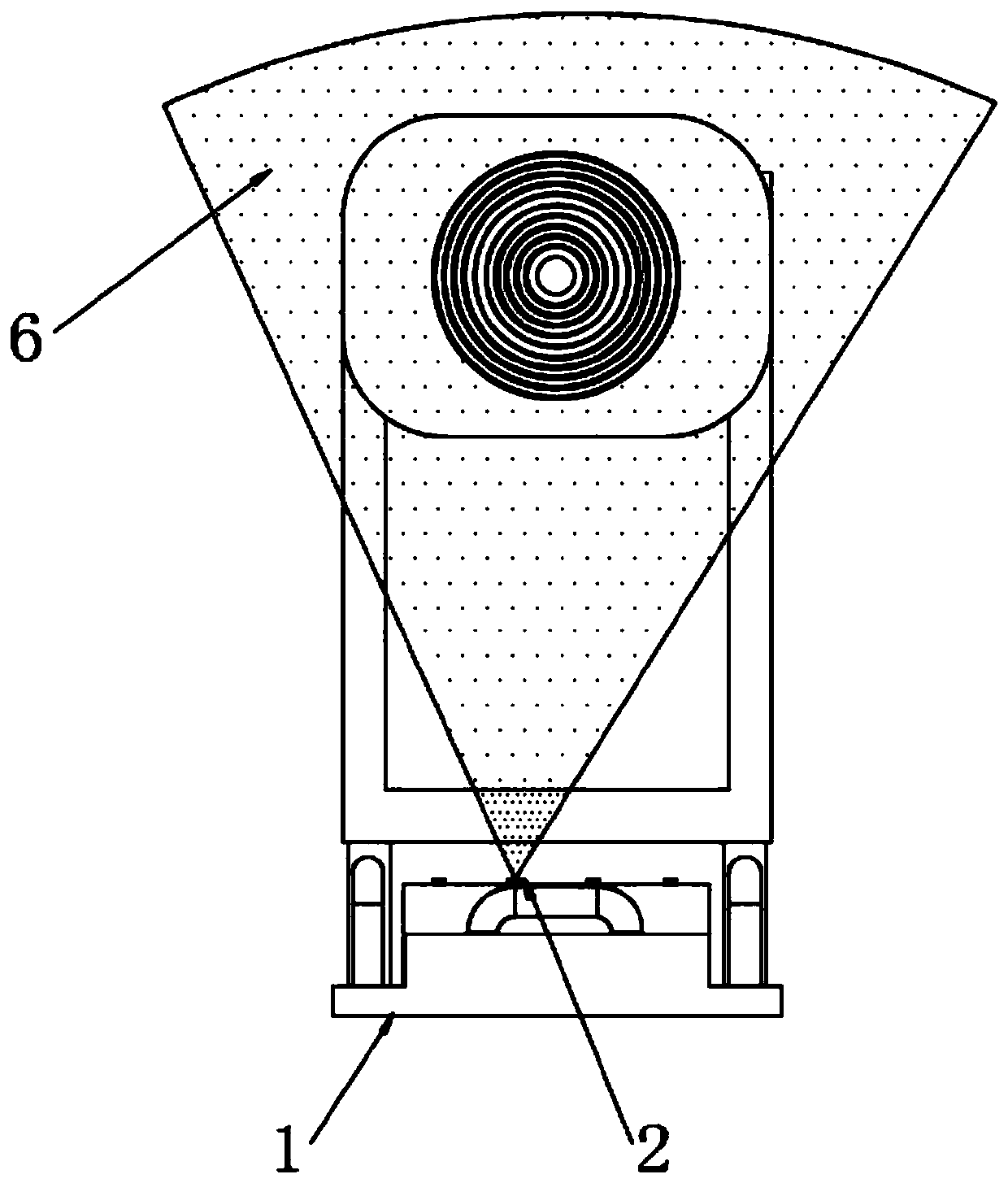
[0026] Embodiment 1: as Figure 1-3 As shown, the present invention provides a technical solution, a laser target reporting device, including a base 1, a laser emitting port 2 is installed on one side of the top of the base 1, and a laser receiving port is installed on the top of the base 1 adjacent to the laser emitting port 2 Port 3, the number of laser receiving ports 3 is three, a support frame 4 is fixedly installed at one end of the base 1, a target surface 5 is fixedly installed on the top side of the support frame 4, and a laser curtain 6 is emitted from the laser emission port 2.

[0027] In order to facilitate the better projection of the points on the laser curtain 6 onto the target surface 5, obtain the number of targets, and report missing missiles in a certain area for easy correction, the laser curtain 6 is parallel to the target surface 5, and the laser curtain 6 The radiation area is greater than the area of ​​the target surface 5.

[0028] When the user uses...

Embodiment 2

[0039] Embodiment 2: as Figure 1-3 As shown, a laser target reporting device includes a base 1, a laser emitting port 2 is installed on one side of the top of the base 1, a laser receiving port 3 is installed at the top of the base 1 adjacent to the laser emitting port 2, and the laser receiving port 3 The number is three, the support frame 4 is fixedly installed on one end of the base 1, the target surface 5 is fixedly installed on the top side of the support frame 4, and the laser curtain 6 is emitted from the laser emission port 2.

[0040] In order to facilitate the better projection of the points on the laser curtain 6 onto the target surface 5, obtain the number of targets, and report missing missiles in a certain area for easy correction, the laser curtain 6 is parallel to the target surface 5, and the laser curtain 6 The radiation area is greater than the area of ​​the target surface 5.

[0041] When the user uses the target, the support frame 4 is fixed on one side ...


PUM


Abstract

The invention discloses a laser target reporting system. The laser target reporting system comprises a base, a laser emitting port is formed in one side of the top end of the base, laser receiving ports are formed in the position, adjacent to the laser emitting port, of the top end of the base, and the number of the laser receiving ports is three, a supporting frame is fixedly installed at one endof the base, a target surface is fixedly installed on one side of the top end of the supporting frame, and pipe orifices of the laser receiving ports emit laser screens. According to the laser targetreporting system, the structure is scientific and reasonable, the use is convenient, the laser target reporting system is simple in structure, convenient to install, free of professional personnel operation, low in manufacturing cost, simple in system calculation, small in calculation amount, high in precision and high in reaction speed block, can be used for multiple times, cannot be scrapped atone time, and avoids waste of resources; and the area of the laser screens is larger than that of the target surface, so that the miss projectile in a certain range can be reported and the correctionis facilitated.

Description

technical field [0001] The invention relates to the technical field of shooting training systems, in particular to a laser target reporting system. Background technique [0002] In the design training, assessment, and competition of troops or athletes, the accuracy and convenience of target reporting are very important; the existing target reporting technologies include electrode embedding, photoelectric sensing, image processing and acoustic-electric positioning Among them, the target judgment method of the electrode embedded type target reporting is one-time, and the target body will be scrapped after each shooting, which leads to the high cost of the electrode embedded type target reporting system. The manufacture of the photoelectric sensor type automatic target reporting system And maintenance costs are high, the manufacturing cost of the image processing automatic target reporting system is high, the calculation is relatively complicated and the amount of calculation i...

Claims


Application Information

Patent Timeline
Patent Type & Authority Applications(China)
IPC IPC(8): F41J5/02
CPCF41J5/02
Inventor 赵玉忠卢士国李宏达
Owner 南京拓恒无人系统研究院有限公司
Learn More