In-situ micro mechanical test board

A test bench, miniature technology, applied in the direction of testing material strength by applying repetitive force/pulsation force, testing material strength by applying stable tension/compression, and measuring devices, which can solve the problem that the fatigue dynamic test cannot be realized and the driving structure is not ideal and other problems, to achieve the effect of fine control, reasonable and compact structure, and reduce the minimum value of strain rate

Active Publication Date: 2019-11-22
杭州源位科技有限公司
View PDF27 Cites 3 Cited by
  • Summary
  • Abstract
  • Description
  • Claims
  • Application Information

AI Technical Summary

Problems solved by technology

The driving structure in which the screw nut and the fixture support frame are rigidly connected along the axial direction of the screw

Method used


Image

  • In-situ micro mechanical test board
  • In-situ micro mechanical test board
  • In-situ micro mechanical test board

Examples


Embodiment 1

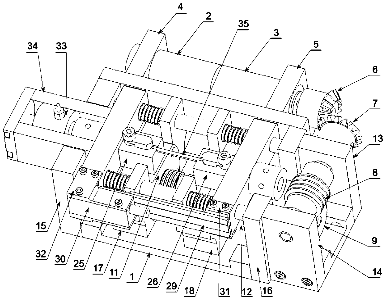
[0052] refer to Figure 1 to Figure 2 As shown, this embodiment provides a single-screw driven in-situ micro-mechanical test bench, including a motor actuator, a spring auxiliary loading mechanism, a position sensing mechanism, a force sensing mechanism and a base 1, and the output winding of the motor 2 The axial rotary motion is converted into the linear motion of the spring auxiliary loading mechanism through steering and transmission. The spring auxiliary loading mechanism applies the load on the tested sample 35, and the position sensing mechanism detects the relative position change of the spring auxiliary loading mechanism in real time and Given the deformation of the sample 35, the force sensing mechanism detects the stress value of the sample 35 in real time.

[0053] The motor actuator includes a motor 2, a reducer 3, a first motor support base 4, a second motor support base 5 and a transmission mechanism. The output end of the motor 2 is connected to the input end ...

Embodiment 2

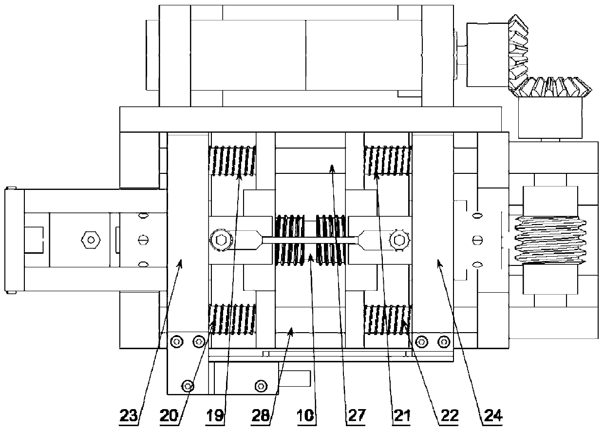
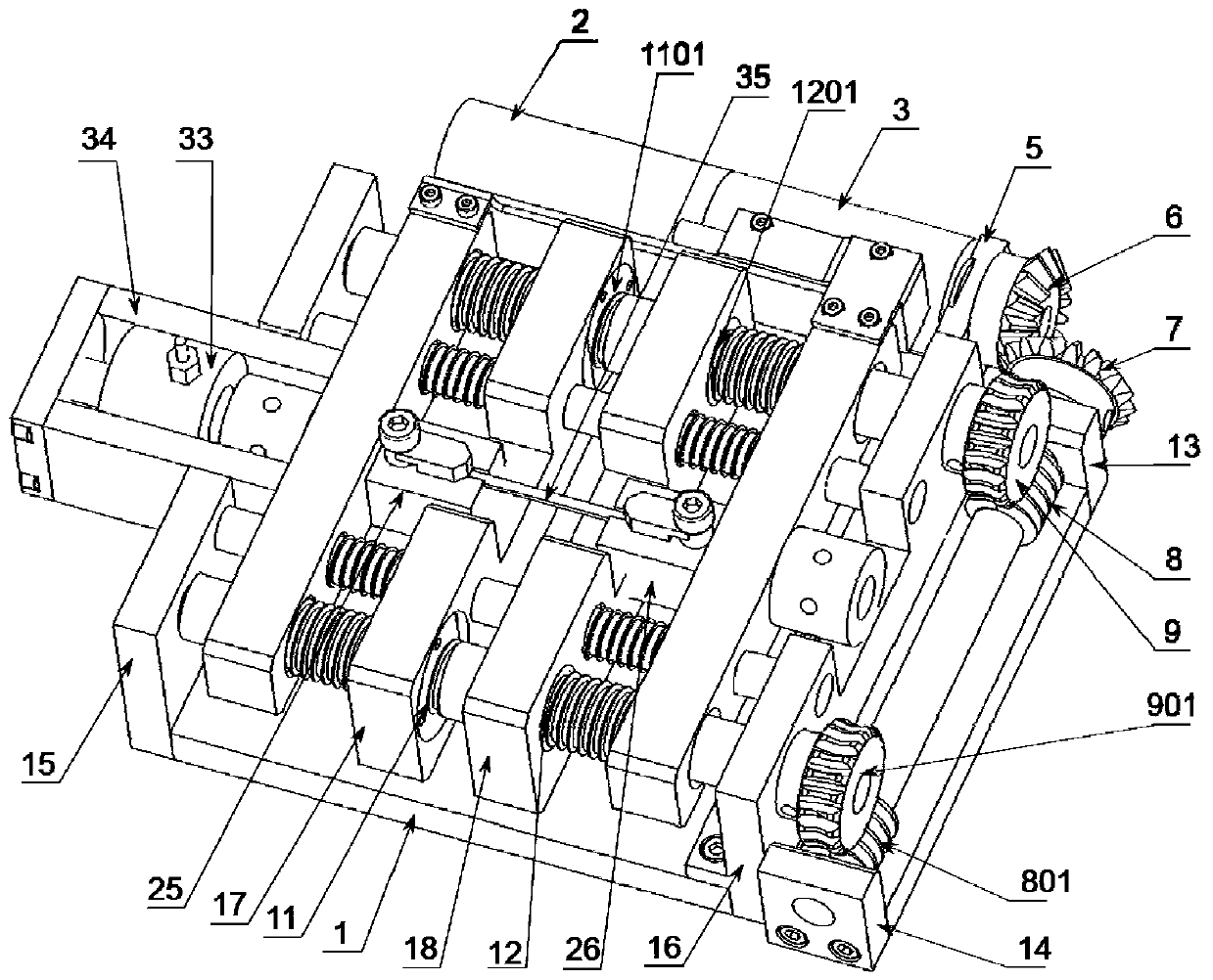
[0061] refer to Figure 3 to Figure 4 As shown, this embodiment provides a double-screw-driven in-situ micro-mechanical test bench. The structure of this embodiment is basically the same as that of Embodiment 1. The difference is that it adopts a transmission mechanism with double screws. The transmission mechanism includes a driving wheel 6, a driven wheel 7, a first worm 8, a second worm 801, a first Worm wheel 9, second worm wheel 901, first screw mandrel 10, second screw mandrel 1001, first nut 11, second nut 12, third nut 1101, fourth nut 1201, first worm screw support seat 13, second worm screw The supporting base 14 , the first screw supporting base 15 and the second screw supporting base 16 .

[0062] The first worm 8 and the second worm 801 are arranged at the two ends on the same worm shaft, and the worm shaft is installed on the first worm support seat 13 and the second worm support seat 14, above the middle part of the first worm 8 and the second worm 801 The fir...


PUM


Abstract

The invention relates to the technical field of in-situ characterization of mechanical properties and microstructure of materials and provides an in-situ micro mechanical test board. The test board comprises a motor execution mechanism, a spring auxiliary loading mechanism, a position sensing mechanism, a force sensing mechanism and a base, wherein the motor execution mechanism is fixed on the base, rotation output of a motor around the axial direction is converted into linear motion of the spring auxiliary loading mechanism through steering and transmission, the spring auxiliary loading mechanism applies a load to a sample, the position sensing mechanism detects the relative position variation, namely the sample deformation quantity, of the spring auxiliary loading mechanism in real time,and the force sensing mechanism detects a stress value borne by the sample in real time. The test board is advantaged in that a clamp supporting frame and a lead screw nut pair are elastically connected in the axial direction of a lead screw, on the basis, a load oscillator is additionally arranged, so fatigue performance testing of the sample and in-situ characterization of the microstructure morphology, chemical components, the crystal structure and the phase structure information of the material under the action of the fatigue load can be realized, the structure is reasonable and compact,and fine control under a force control mode is facilitated.

Description

technical field [0001] The invention relates to the technical field of in-situ characterization of material mechanical properties and microstructure, in particular to an in-situ micro-mechanical test bench. Background technique [0002] The in-situ micro-mechanical test bench is a small-scale mechanical test platform compatible with scanning electron microscope (SEM), backscattered electron diffraction (EBSD), X-ray diffractometer (XRD) and optical microscope (OM) and other microstructure test platforms. performance testing equipment. The in-situ micro-mechanical test bench can be used to perform mechanical tests on materials and obtain corresponding stress-strain curves. With the help of the above-mentioned micro-test platform, the microstructure, chemical composition, crystal structure and phase structure information of materials under specific loads can be analyzed. Characterization analysis, the analysis range spans from the macroscopic to the nanometer scale. Based on...

Claims


Application Information

Patent Timeline
IPC IPC(8): G01N3/06G01N3/16G01N3/32
CPCG01N3/06G01N3/16G01N3/32G01N2203/0003G01N2203/0005G01N2203/0017G01N2203/0019G01N2203/005G01N2203/0073G01N2203/0641
Inventor 李吉学党理
Owner 杭州源位科技有限公司
Why Eureka
Try Eureka