
Efficient detection device for polymer cable production

A detection device and polymer technology, applied in the direction of measuring devices, using mechanical devices, analyzing materials, etc., can solve the problems of high manufacturing cost and poor detection effect, and achieve the goal of reducing production cost, enhancing the scope of use, and ensuring accuracy Effect

Inactive Publication Date: 2019-11-22
JING FENG GRP
View PDF13 Cites 3 Cited by
  • Summary
  • Abstract
  • Description
  • Claims
  • Application Information

AI Technical Summary

Problems solved by technology

[0003] The purpose of the present invention is to solve the problem of high manufacturing cost and poor detection effect in the prior art, and propose a high-efficiency detection device for polymer cable production

Method used


Image

  • Efficient detection device for polymer cable production
  • Efficient detection device for polymer cable production
  • Efficient detection device for polymer cable production

Examples


Embodiment 1

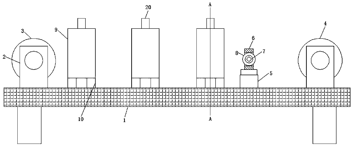
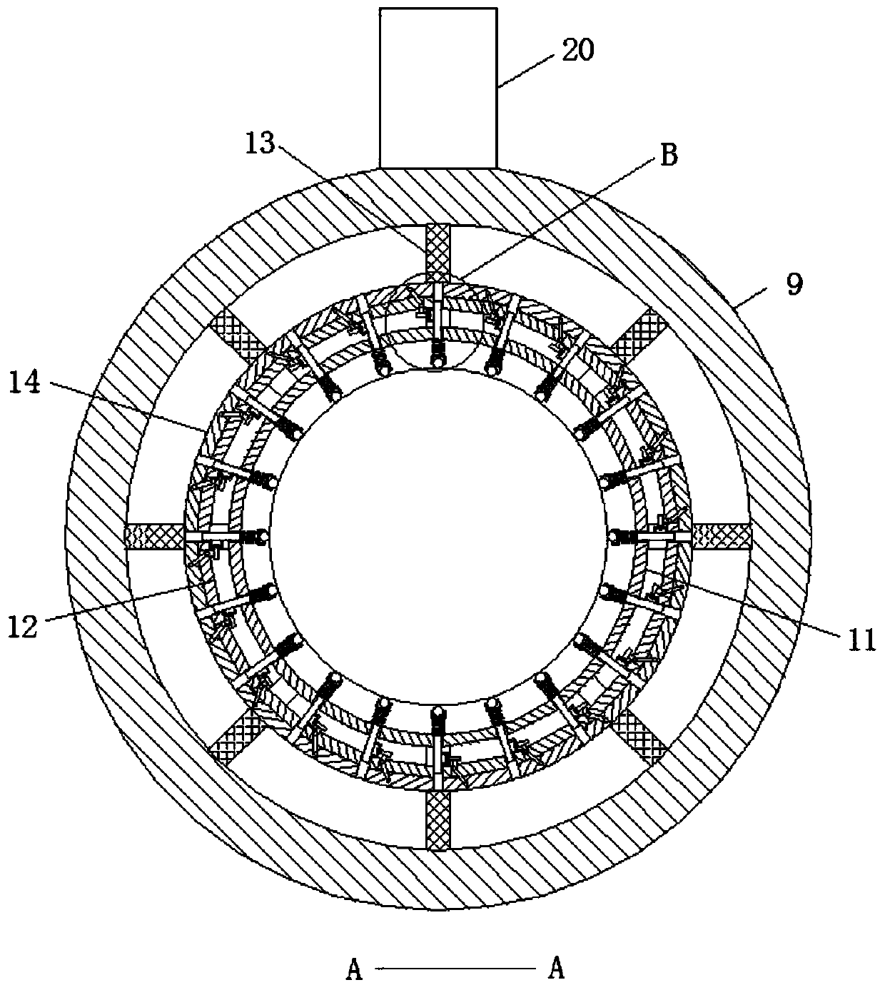
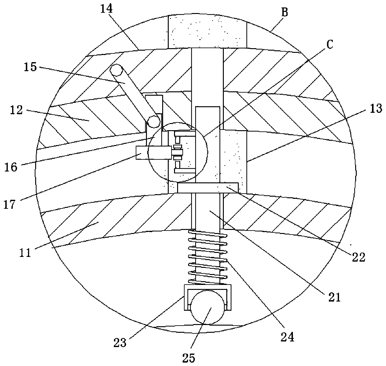
[0026] refer to Figure 1-4 , a high-efficiency detection device for polymer cable production, including a detection platform 1, the four corners of the lower end surface of the detection platform 1 are fixedly connected with support legs by screws, and both sides of the upper end surface of the detection platform 1 are fixedly connected with support seats by screws 2. There are two support bases 2, a take-up roller 3 and a pay-off roll 4 are respectively installed between the two support bases on the same side, and a detection ring 9 is provided in the middle of the detection table 1, and the detection ring 9 is provided with three One, both sides of the lower end of the detection ring 9 are welded with fixed columns 10, the lower end of the fixed column 10 is fixed on the detection platform 1 by screws, the inner side of the detection ring 9 is provided with an installation ring 11, and the outer side of the installation ring 11 is provided with an adjustment ring 12 , the m...

Embodiment 2

[0029] Such as figure 1 As shown, this embodiment is basically the same as Embodiment 1. Preferably, the side of the upper end surface of the detection table 1 close to the pay-off roller 4 is fixedly connected with a cylinder 5 by screws, and the output end of the cylinder 5 is fixedly connected with a guide plate 6 by screws. The side wall of guide plate 6 runs through and is provided with rectangular hole, and between the front and rear end sidewalls of rectangular hole, is connected with installation rod 7 by rolling bearing rotation, and the rod outer wall of installation rod 7 is fixedly connected with guide wheel 8 by key.

[0030] In this embodiment, through the cooperative use of the cylinder 5, the guide plate 6, the installation rod 7 and the guide wheel 8, it is ensured that the cable enters the detection ring in a horizontal position, and the sound alarm 20 is prevented from being squeezed by the gravity on the lower ball of the cable. The occurrence of the alarm ...

Embodiment 3

[0032] Such as Figure 1-4 As shown, this embodiment is basically the same as Embodiment 1. Preferably, the control switches 19 are electrically connected to the sound alarm 20 through wires.

[0033] In this embodiment, the control switch 19 is connected to the sound alarm 20 through wires, so as to ensure that the sound alarm 20 will generate an alarm after the control switch is squeezed.


PUM


Abstract

The invention discloses an efficient detection device for polymer cable production, which includes a detection platform. The four corners of the lower end face of the detection platform are fixedly connected with support legs through screws. The two sides of the upper end face of the detection platform are fixedly connected with support seats through screws, and two support seats are arranged on each side. A take-up roller and a pay-off roller are installed between the two support seats on the same side. Three detection rings are arranged in the middle of the detection platform. Fixed columnsare welded on the two sides of the lower end of each detection ring. The lower ends of the fixed columns are fixed on the detection platform by screws. An installation ring is arranged on the inner side of each detection ring. An adjustment ring is arranged on the outer side of each installation ring. Support rods are respectively fixed between the installation rings and the adjustment rings on one hand and the inner walls of the detection rings on the other hand by screws. The outer wall of each adjustment ring is rotationally connected with a rotating ring through rolling bearings. A connecting rod is hinged to the side wall of one end of each rotating ring. A sliding slot is formed in the side wall of one end, close to the connecting rod, of each adjustment ring.

Description

technical field [0001] The invention relates to the technical field of cable production detection equipment, in particular to a high-efficiency detection device for polymer cable production. Background technique [0002] Surface defects such as bulges, pits, exposed lines, peeling, scratches, and uneven thickness are prone to appear on the surface of polymer cables during production. The existing laser pens are installed around the cables, and then according to the imaging of the laser pen To judge whether the current cable sheath has problems such as bulges, holes, and abnormal diameters. Due to the relatively small diameter of the cable, it is difficult to lay the laser displacement sensor, and it is inconvenient to mediate when detecting cables of different specifications. In addition, the laser displacement sensor The cost of equipment is high, and it is difficult to meet the needs of production, so it is necessary to study a high-efficiency detection device for polymer ...

Claims


Application Information

Patent Timeline
IPC IPC(8): G01N19/08G08B3/10
CPCG01N19/08G08B3/10
Inventor 许义彬许德俊刘文林
Owner JING FENG GRP
Learn More