
Non-destructive detection method and application based on micro-motion three-component spectral ratio vhsr

A non-destructive detection, three-component technology, applied in the field of engineering geophysical detection, can solve the problems of fast signal attenuation, limited detection depth, electromagnetic interference, etc., and achieve the effect of strong anti-interference ability

Active Publication Date: 2021-11-02
ARCHITECTURAL DESIGN INST FUKIEN PROV
View PDF13 Cites 0 Cited by
  • Summary
  • Abstract
  • Description
  • Claims
  • Application Information

AI Technical Summary

Problems solved by technology

Commonly used to detect obstacles, such as ground penetrating radar, in southern cities with shallow groundwater levels, the signal attenuation is fast, the detection depth is limited, and at the same time, it is also affected by electromagnetic interference, so the effect is often not ideal; various cross-hole CT methods have certain effects. However, the effects of different methods between the holes are not the same, and are affected by the hole spacing, not only the cost is high, but the construction period is long
In general, many geophysical methods fail to achieve the expected results in the complex urban environment

Method used


Image

  • Non-destructive detection method and application based on micro-motion three-component spectral ratio vhsr
  • Non-destructive detection method and application based on micro-motion three-component spectral ratio vhsr
  • Non-destructive detection method and application based on micro-motion three-component spectral ratio vhsr

Examples


Embodiment 1

[0056] Example 1: Detection of pile foundation position and pile length in a subway shield section by VHSR method

[0057] Project overview: Obstacle survey data show that the pile foundation of a flyover (the part above the ground has been demolished) in the shield tunnel section of a subway is located within the tunnel body of the shield tunnel, but there are doubts, so the VHSR method is used to detect and find out. The bedrock surface was not revealed at the end hole 47.8m of the nearby detailed survey drilling hole MDZ3-29-34, and the main soil layers from top to bottom are miscellaneous fill, silty clay, silt, silty clay, silt, silty clay, sandy soil Strongly weathered granite.

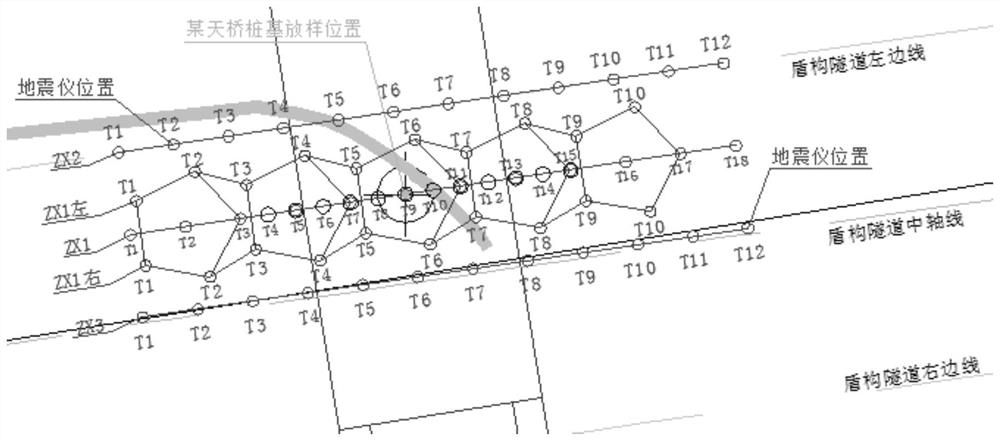
[0058] Step 1: This VHSR method detection uses a three-component high-precision integrated digital seismograph, and arranges two-dimensional three-component geophone arrays at intervals of 0.5 to 1.5 m (see figure 2 ), collect surface micro-vibration signals for 10-15 minutes;

[0059] Step 2...

Embodiment 2

[0064] Example 2: VHSR method detection of artificial rockfill range in the range of foundation pit support in a construction site

[0065] Project overview: The survey data reveals the distribution characteristics of the main rock and soil layers in the survey area as follows: (1) Miscellaneous fill (local silty clay), silt (soil) mixed with sand, silt, silty clay, silt (soil) , silty clay, round breccia, crushed pebbles, silty soil, sandy strongly weathered, fragmented strongly weathered and moderately weathered tuff, etc. The bedrock is buried at a depth of about 45m. The planned road is on the edge of the survey area. During construction, local rock filling may invade the construction range of the foundation pit support and enclosure piles, which will affect the later construction of the foundation pit support and enclosure piles. Unfavorable geological bodies such as rockfill that may exist within the pile construction range are detected by the non-destructive VHSR method...


PUM


Abstract

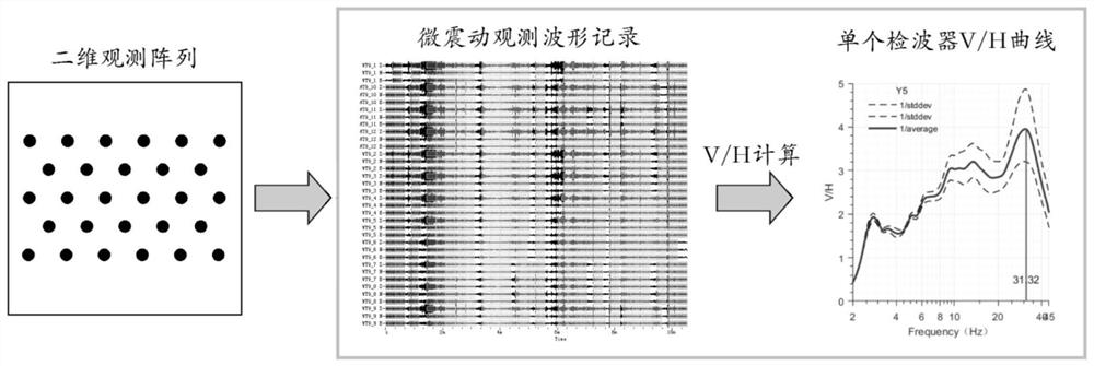
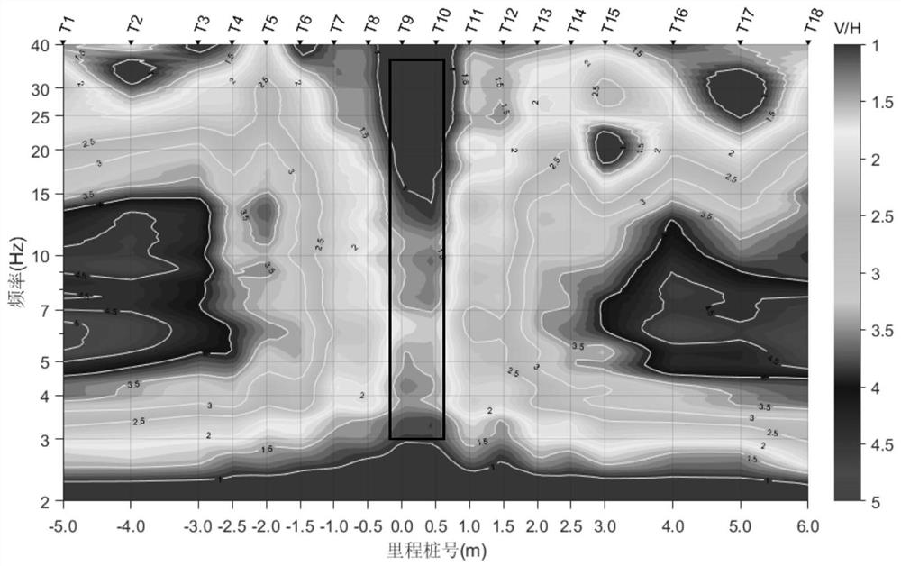
The invention is a non-destructive detection method and application based on the micro-motion three-component spectral ratio VHSR. The method includes the following steps: 1. Collect the surface micro-vibration signals of the two-dimensional array; 2. Calculate the VHSR curves of the data collected by each three-component geophone; 3. Use the self-developed MATLAB program to form the VHSR curves of each measuring point into two 3D VHSR curve contour map or 3D slice map; 4. According to the abnormal characteristics of the 2D VHSR curve contour map or 3D slice map, infer and explain the abnormal target body. This method is used in the detection of underground obstacles or bad geology that affect engineering construction, such as pile foundations, caps, pipes, artificial rock filling, cavities, weak interlayers, etc. The invention can accurately ascertain the distribution range of underground obstacles and bad geology, discover potential risks in advance for shield tunneling, pipe jacking and other urban engineering constructions, avoid major construction accidents, and has a great effect.

Description

technical field [0001] The invention relates to an engineering geophysical detection method, in particular to underground obstacles affecting engineering construction such as pile foundations, caps, pipelines, artificial rock filling, cavities, and weak interlayers within the depth range of shallow ground or covering layers in urban engineering construction. Non-destructive detection method and application based on micro-motion three-component spectral ratio VHSR for object or bad geological detection. Background technique [0002] In urban engineering construction, pile foundations, caps, pipes, artificial rock filling, cavities, weak interlayers, etc. within the shallow surface or the depth of the covering layer often affect or harm the engineering construction. For example, if an unexplored pile foundation is encountered during the tunneling of the shield machine, it will often seriously damage the shield machine, and even cause accidents such as spewing and landslides; w...

Claims


Application Information

Patent Timeline
Patent Type & Authority Patents(China)
IPC IPC(8): G01V1/28G01V1/36
CPCG01V1/28G01V1/36
Inventor 刘宏岳殷勇刘俊龙黄佳坤张红梅林孝城林荣吴明和
Owner ARCHITECTURAL DESIGN INST FUKIEN PROV
Learn More