
Molding cooling device for processing outer insulating layer of power cable

A technology of outer insulation layer and power cable, which is applied in the direction of conductor/cable insulation, cable/conductor manufacturing, circuit, etc., can solve the problem of high processing temperature of outer insulation layer of power cable, inability to cool the outer insulation layer of cable, low cooling efficiency, etc. problems, to achieve high social use value and application prospects, avoid waste of water resources, and improve the effect of cooling efficiency

Inactive Publication Date: 2019-11-22
涌纬集团股份有限公司
View PDF5 Cites 2 Cited by
  • Summary
  • Abstract
  • Description
  • Claims
  • Application Information

AI Technical Summary

Problems solved by technology

[0002] At present, when the existing outer insulating layer of power cables is processed, the processing temperature of the outer insulating layer of the processed power cable is relatively high, and it cannot be wound into a coil even if it is wound into a coil. The outer insulation layer of the cable is shaped
[0003] The existing cooling device for the outer insulating layer of cables is not very mature. It is not very convenient to operate when cooling the outer insulating layer of cables, and the cooling efficiency is not high.
The traditional cooling device for the processing of the outer cable insulation layer prevents the operator from cooling the cable outer insulation layer very conveniently, which wastes a lot of manpower and increases the production cost of the cable outer insulation layer to a large extent. Most cooling devices use direct immersion cooling, the temperature of the cooling water will rise quickly, thereby reducing the cooling efficiency, and at the same time wasting a certain amount of water resources, which will bring great losses to production. In view of the above reasons, it is proposed A plastic cooling device for processing the outer insulating layer of power cables

Method used


Image

  • Molding cooling device for processing outer insulating layer of power cable
  • Molding cooling device for processing outer insulating layer of power cable
  • Molding cooling device for processing outer insulating layer of power cable

Examples


Embodiment 1

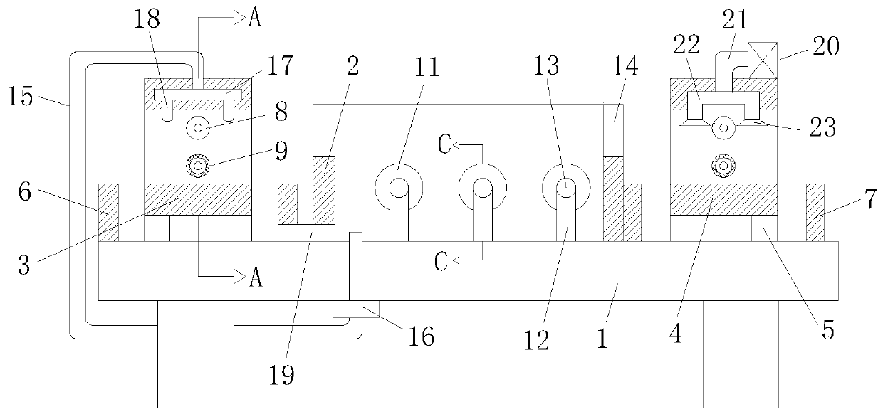
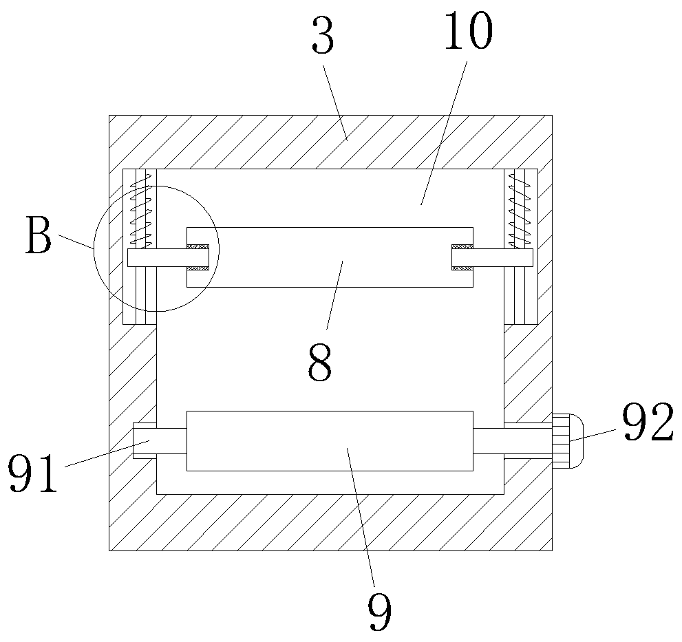
[0030] refer to Figure 1-2 , Figure 4-6 , a plastic cooling device for processing the outer insulating layer of a power cable, comprising a workbench 1 and, the upper end of the workbench 1 is provided with a spray chamber 3, a temperature-reducing water tank 2 and an air-drying chamber 4 in sequence from left to right. The bottoms of the chamber 3 and the air-drying chamber 4 are respectively fixedly connected with a fixed frame 5, the upper end of the workbench 1 and the outside of the spray chamber 3 are provided with a water storage tank 6, and several rollers 11 are equidistantly arranged in the cooling water tank 2, And the two ends of the roller 11 are respectively horizontally connected with a connecting shaft 13, the outer wall of the connecting shaft 13 is sleeved with a fixed rod 12, and the fixed rod 12 is fixed on the inner bottom of the temperature-reducing water tank 2, and the spray chamber 3 and the air-drying chamber 4 are respectively A transmission openi...

Embodiment 2

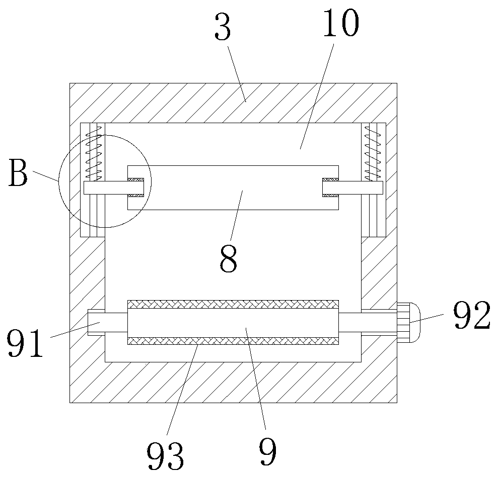
[0038] refer to figure 1 and Figure 3-6 , The difference between this embodiment and Embodiment 1 is that, wherein, the outer wall of the conveying roller 9 is provided with a layer of anti-slip rubber pad 93, and the anti-slip rubber pad 93 is a member made of rubber material, and the outer wall of the anti-slip rubber pad 93 is provided with anti-skid lines , Increase the surface friction of the conveying roller 9, which helps the transmission of the cable.

[0039] Refer to Example 1 for other undescribed structures.

[0040] Working principle: In the present invention, in the present invention, when in use, the cable to be cooled enters through the spray chamber 3, and passes through the cooling water tank 2 and then is output from the drying chamber 4. When the cable enters the spray chamber 3, The pinch roller 8 presses down the cable to the outer wall of the transmission roller 9. Since both ends of the pinch roller 8 are horizontally connected with connecting shafts...


PUM


Abstract

The invention discloses a molding cooling device for processing an outer insulating layer of a power cable. The device comprises a workbench; a spraying chamber, a cooling water tank and an air dryingchamber are sequentially arranged at the upper end of the workbench from left to right. The bottom of the spraying chamber and the bottom of the air drying chamber are fixedly connected with fixing frames correspondingly. A water storage tank is arranged at the upper end of the workbench and located outside the spraying chamber. A plurality of rolling shafts are arranged in the cooling water tankat equal intervals, the two ends of each rolling shaft are horizontally connected with connecting shafts correspondingly, the outer walls of the connecting shafts are sleeved with fixing rods, the fixing rods are fixed to the inner bottom of the cooling water tank, conveying openings are formed in the spraying chamber and the air drying chamber correspondingly, and pressing rollers and conveyingrollers are arranged at the upper ends and the lower ends in the conveying openings correspondingly. The molding cooling device overcomes the defects in the prior art, is reasonable in design, conducts pre-spraying before the cable enters the cooling water tank, improves the cooling efficiency, can recycle spraying water, saves water resources, and has high social use value and application prospects.

Description

technical field [0001] The invention relates to the technical field of cables, in particular to a molding cooling device for processing the outer insulating layer of a power cable. Background technique [0002] At present, when the existing outer insulating layer of power cables is processed, the processing temperature of the outer insulating layer of the processed power cable is relatively high, and it cannot be wound into a coil even if it is wound into a coil. The outer insulation layer of the cable is shaped. [0003] The existing cooling device for the outer insulating layer of the cable is not very mature, and it is not very convenient to operate when cooling the outer insulating layer of the cable, and the cooling efficiency is not high. The traditional cooling device for the processing of the outer cable insulation layer prevents the operator from cooling the cable outer insulation layer very conveniently, which wastes a lot of manpower and increases the production ...

Claims


Application Information

Patent Timeline
Patent Type & Authority Applications(China)
IPC IPC(8): H01B13/00H01B13/06H01B13/30
CPCH01B13/0036H01B13/06H01B13/30
Inventor 李国宝郑桂东尹华顺
Owner 涌纬集团股份有限公司
Learn More