Front output overspeed ratio speed reduction large-torque motor

A high torque, motor shaft technology, applied in the direction of electrical components, electromechanical devices, electric components, etc., can solve the problems that affect the high torque output of the motor shaft and power output shaft, inconvenient maintenance, high production cost, etc., to ensure the output torque and rigidity Need, easy maintenance, simple structure effect

Pending Publication Date: 2019-11-22
ZHEJIANG DONGBA TRANSMISSION
View PDF0 Cites 0 Cited by
  • Summary
  • Abstract
  • Description
  • Claims
  • Application Information

AI Technical Summary

Problems solved by technology

[0003] In the existing technology, the combination of the reducer and the motor is more common. In order to increase the torque, the reducer casing must be designed separately. This combination looks like a reducer. The slip ratio is extremely large when the speed is changed, and the large speed ratio cannot be realized.
[0004] Using the existing motor standards to design motors with reduction devices generally use planetary reduction mechanisms to cooperate with the motor, but most of them have the following deficiencies: A. Generally, the reduction ratio is low, and it can only be reduced by several times, which cannot meet the speed ratio requirements. , B. Due to the limitation of the planetary deceleration structure, the output torque cannot meet the requirements. C. Due to the influence of the planetary deceleration structure, the structure is relatively complicated and not easy to maintain. The planetary deceleration structure adopts the concentric sleeve shaft of the motor shaft and the power output shaft method, the production cost is high, and it is easy to be damaged. At the same time, the high torque output of the motor shaft and the power output shaft is affected by the sleeve shaft method.

Method used


Image

  • Front output overspeed ratio speed reduction large-torque motor
  • Front output overspeed ratio speed reduction large-torque motor
  • Front output overspeed ratio speed reduction large-torque motor

Examples


Embodiment Construction

[0021] The specific embodiments of the present invention will be further described in detail below in conjunction with the accompanying drawings.

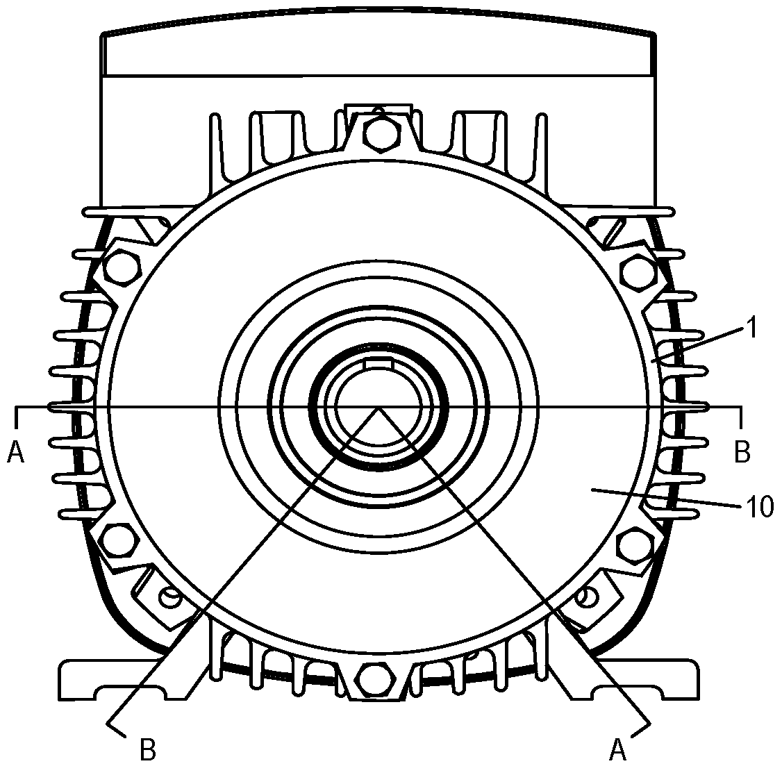
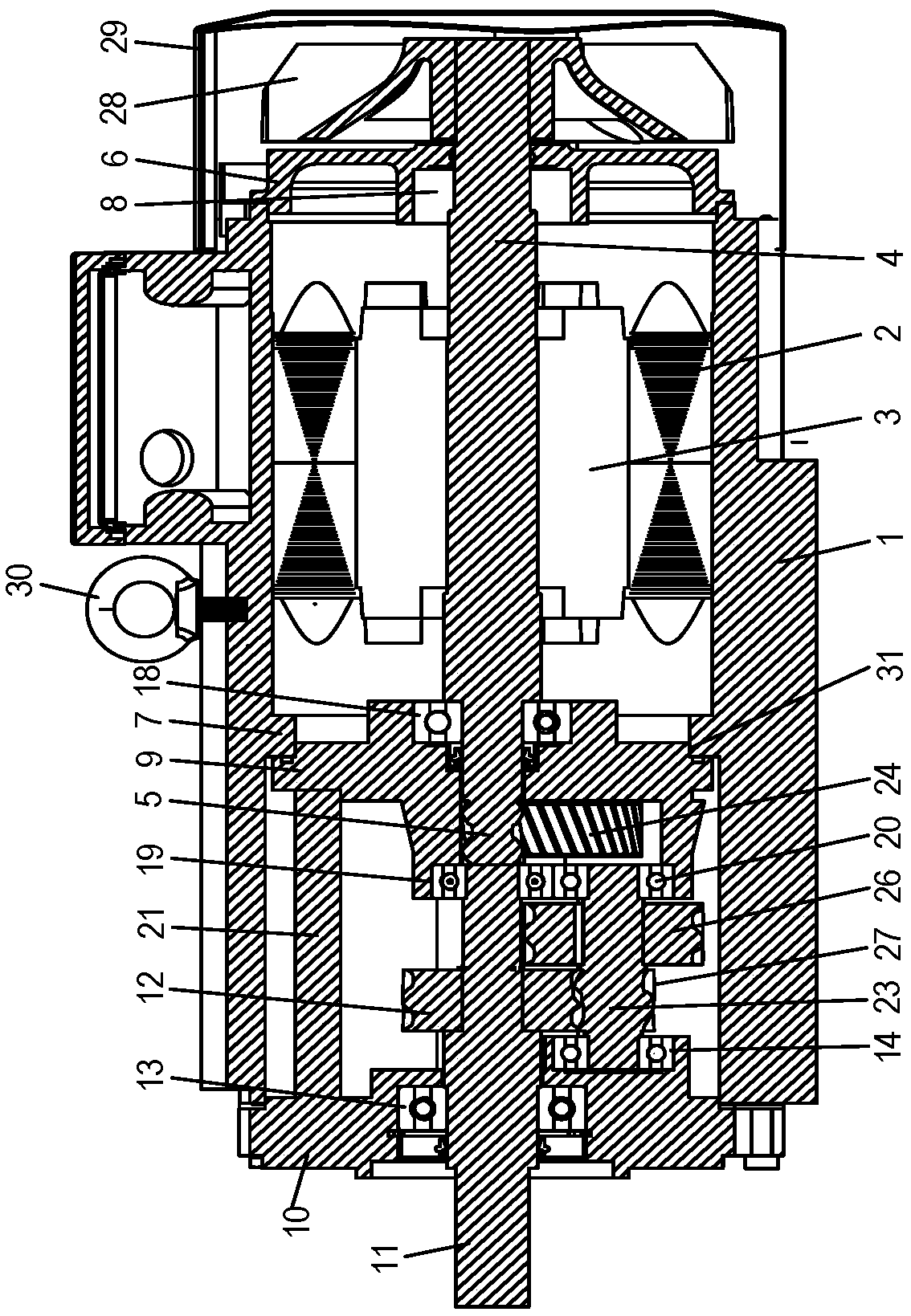
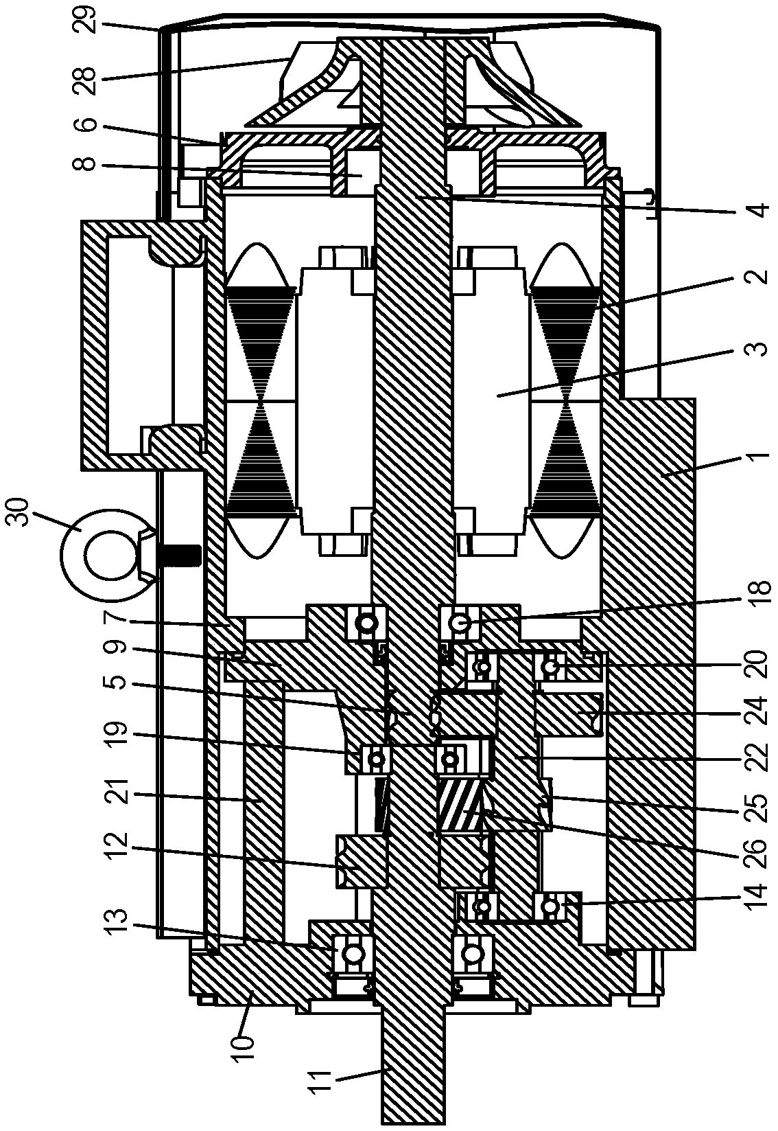
[0022] Such as figure 1 and Figure 6 As shown, the front output overspeed ratio reduction high-torque motor related to the present invention includes a motor housing 1, a motor stator 2, a motor rotor 3, a motor shaft 4, a driving wheel 5 and a rear end cover 6, and the middle of the inner wall of the motor housing 1 A spigot protruding ring 7 integrally connected with the motor casing 1 is provided, the motor stator 2 is fixed in the rear of the motor casing 1, the motor rotor 3 is arranged in the motor stator 2, the motor shaft 4 is fixed in the motor rotor 3, and the driving wheel 5 is set on the front end of the motor shaft 4, the rear end cover 6 is fixed on the rear end of the motor casing 1, the rear support 8 of the motor shaft is set on the center position of the rear end cover 6, and the rear part of the motor shaft 4 i...


PUM


Abstract

The invention relates to a front output overspeed ratio speed reduction large-torque motor. The motor comprises a motor shell, a motor stator, a motor rotor, a motor shaft, a driving wheel and a rearend cover; the device further comprises a suspension torque flange, a power output flange, a power output shaft, a driven wheel and a multi-shaft linkage device. According to the technical scheme, a flange ring is arranged in the middle of a motor cavity; a multi-shaft helical gear transmission device and the motor form an all-in-one machine; the invention aims to solve the defects in the prior art, and provides an energy-saving and environment-friendly product which can effectively reduce a mechanical friction coefficient, increase the torque by several times to dozens of times on the basis of a standard motor, achieve the ultrahigh energy efficiency value in efficiency, and is high in space saving value, novel in appearance, high in protection grade and convenient to install.

Description

technical field [0001] The invention relates to a deceleration motor, in particular to a front output overspeed ratio deceleration high-torque motor. Background technique [0002] In the prior art, the combination of the reducer and the motor can achieve a certain range of speed change. Not only can the effect of speed change be realized, but also the power of the motor will not be affected, and the torque of the output shaft will increase several to dozens of times. [0003] In the prior art, the combination of the reducer and the motor is more common. In order to increase the torque, the reducer casing must be designed separately. This combination looks like a reducer. The slip ratio is extremely large when the speed is changed, and the large speed ratio cannot be realized. [0004] Using the existing motor standards to design motors with deceleration devices generally use planetary deceleration mechanisms to cooperate with the motor, but most of them have the following de...

Claims


Application Information

Patent Timeline
IPC IPC(8): H02K7/116
CPCH02K7/116
Inventor 余新正柯一杭余成东项裕福谷享广
Owner ZHEJIANG DONGBA TRANSMISSION
Why Eureka
Try Eureka