Tapered roller bearing

A tapered roller bearing and roller technology, applied in the direction of bearings, rolling contact bearings, bearing components, etc., can solve the problems of increasing, or the grinding stone is in contact with the flange, and it is not easy to obtain surface roughness, and achieves easy finishing. , suppress the effect of equipment modification

Inactive Publication Date: 2019-11-22
NSK LTD
View PDF11 Cites 2 Cited by
  • Summary
  • Abstract
  • Description
  • Claims
  • Application Information

AI Technical Summary

Problems solved by technology

[0007] However, in tapered roller bearings and cylindrical roller bearings, since the flange portion is provided on the axially outer side of the raceway surface of the inner ring, when machining a logarithmic convex surface on the raceway surface of the inner ring, it is necessary to use a grindstone When finishing, it is not easy to obtain the desired surface roughness at the end of the raceway surface
In addition, in order to obtain the desired surface roughness, it takes a long time until the grindstone adapts, and the cycle time increases, or the grindstone is in contact with the collar, or it is necessary to add complicated equipment as described in Patent Document 2.

Method used


Image

  • Tapered roller bearing
  • Tapered roller bearing
  • Tapered roller bearing

Examples


no. 1 approach

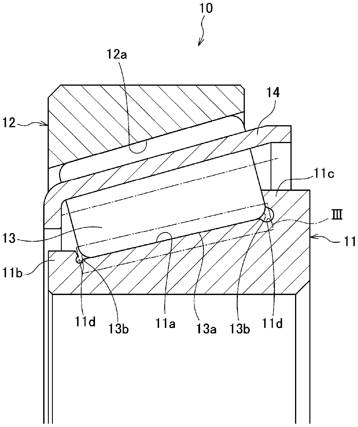
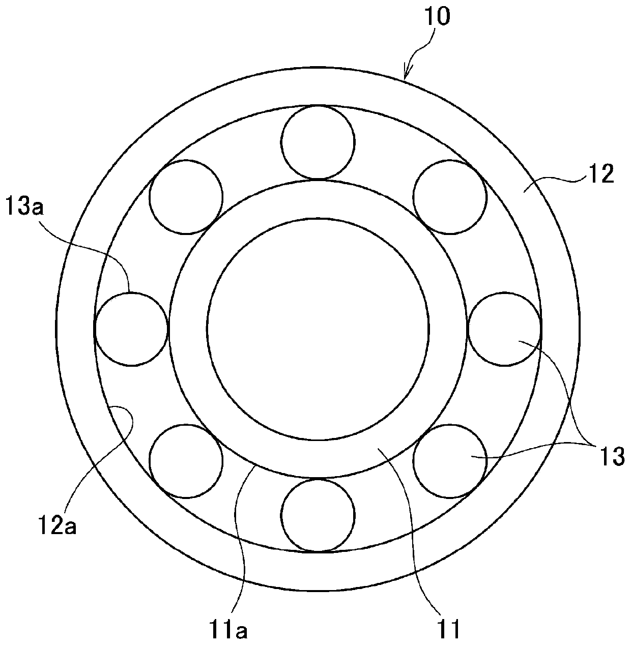
[0056] Such as figure 1 and figure 2 As shown, the tapered roller bearing 10 of this embodiment includes: an inner ring 11, which is provided with an inner ring raceway surface 11a on the outer peripheral surface; an outer ring 12, which is provided with an outer ring raceway surface 12a on the inner peripheral surface; The body is a plurality of tapered rollers 13 (hereinafter, also simply referred to as "rollers 13"), which are arranged between the inner ring raceway surface 11a and the outer ring raceway surface 12a; and the cage 14, which holds a plurality of The rollers 13 are held at predetermined intervals in the circumferential direction.

[0057] The inner ring 11 includes a small-diameter flange portion 11 b and a large-diameter flange portion 11 c at the small-diameter side axial end portion and the large-diameter side axial end portion of the inner ring raceway surface 11 a.

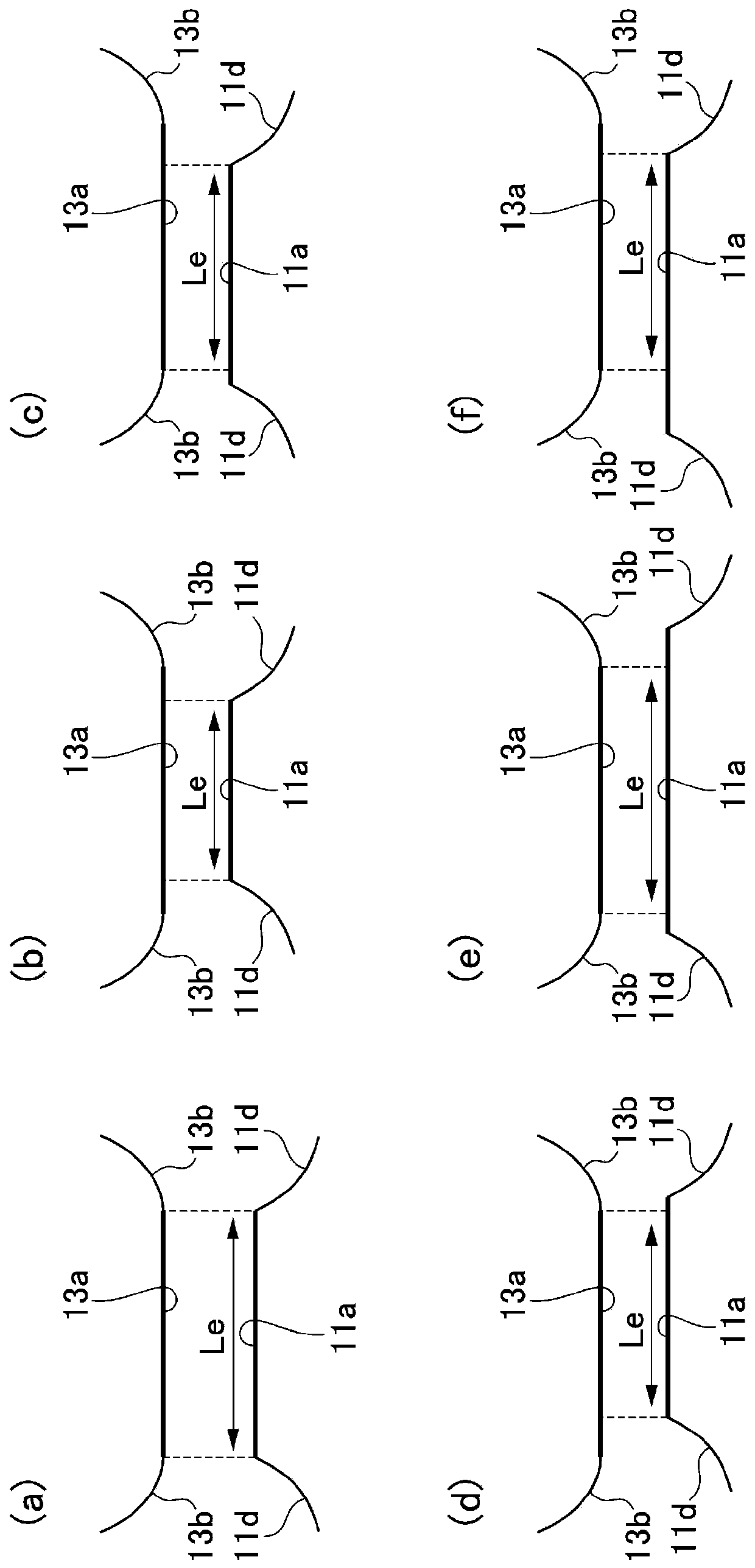
[0058]Furthermore, in this embodiment, in order to suppress the occurrence of edge lo...

no. 2 Embodiment approach

[0097] Next, refer to Figure 7 A tapered roller bearing according to a second embodiment of the present invention will be described. In addition, in this embodiment, the convex shape of the raceway surface of an inner ring and an outer ring, and the rolling surface of a roller differs from 1st Embodiment. Other configurations are the same as those of the first embodiment.

[0098] That is, in the present embodiment, the raceway surface 11a of the inner ring 11 is provided as Figure 7 The shown logarithmic convex surface with a small drop is used instead of the single arc convex surface of the first embodiment. Also in this case, the rolling surface 13a of the roller 13 is formed by subtracting the drop amount of the logarithmic convexity of the inner ring raceway surface 11a from the sum δ of the logarithmic convexity given by the above formula (i). convex shape.

[0099] In addition, in this case, for the crown of the inner ring, the crown drop of the raceway surface 11...


PUM


Abstract

A tapered roller bearing (10) is provided, wherein flange parts (11b, 11c) are provided on one or both ends of an inner ring (11), crowning is provided on both the rolling surface (13a) of the rollers(13) and the raceway surface (11a) of the inner ring (11), and at least at one end of the effective contact length (Le) in the generatrix direction, the amount of crown drop at the raceway surface (11a) of the inner ring (11) is less than the amount of crown drop at the rolling surface (13a) of the rollers (13).

Description

technical field [0001] The invention relates to tapered roller bearings, in particular to tapered roller bearings used in reducers, engineering machinery, steel, automobiles and the like. Background technique [0002] Conventionally, in roller bearings, it is known to provide a convex surface on the rolling surface of the roller or the raceway surface of the raceway wheel in order to suppress excessive contact surface pressure, so-called edge load, at both ends of the contact portion in the axial direction. (For example, refer to Patent Document 1). [0003] As the convex surface, the effective contact length Le in the direction of the generatrix is ​​known, and the contact part is set from the axial center to both ends as a logarithmic convex surface that does not generate excessive contact surface pressure, so-called edge load, so that it can be Achieve long life. [0004] On the other hand, by showing the logarithmic convexity and the single arc convexity together Figu...

Claims


Application Information

Patent Timeline
Patent Type & Authority Applications(China)
IPC IPC(8): F16C33/58F16C33/36
CPCF16C19/364F16C33/366F16C33/585F16C2240/50F16C2300/02F16C23/088F16C33/36
Inventor 前田吉则菅沼宪太郎
Owner NSK LTD
Why Eureka
Try Eureka