Flying shearing machine

A technology for flying shears and workpieces, applied in the field of flying shears, can solve problems such as unreasonable adjustment of side clearance, shear deviation, and irregular shearing, and achieve improved product shearing quality, accurate cutting length, and high productivity. Effect

Inactive Publication Date: 2019-11-26
ANHUI POLYTECHNIC UNIV MECHANICAL & ELECTRICAL COLLEGE
View PDF15 Cites 2 Cited by
  • Summary
  • Abstract
  • Description
  • Claims
  • Application Information

AI Technical Summary

Problems solved by technology

Since the total tension of the steel has a great influence on the disc shearing edge during shearing, it is easy to cause the problem of deviation in shearing, resulting in irregular shearing and easy loss. If the deviation is too serious, the shearing cannot be carried out, thus damaged equipment
In power shearing, both the shear force and the rotating force of the cutter shaft are provided by the motor, and the force in the process of drawing and shearing is transmitted by the unit through the strip steel. The time is much larger, and it is also a major factor that easily causes the deviation of the scissors
At the same time, a disadvantage of disc shearing that cannot be ignored is that the shearing edge fracture is irregular, there are many burrs, the amount of overlap of disc shearing, the adjustment of side clearance is unreasonable, and the strip shearing fails to focus on the small metal deformation. The strong stress concentration generated in the zone forces the strip steel to undergo brittle fracture, etc.

Method used


Image

  • Flying shearing machine
  • Flying shearing machine
  • Flying shearing machine

Examples


Embodiment Construction

[0017] The specific embodiment of the present invention will be described in further detail by describing the embodiments below with reference to the accompanying drawings, the purpose is to help those skilled in the art to have a more complete, accurate and in-depth understanding of the concept and technical solutions of the present invention, and contribute to its implementation.

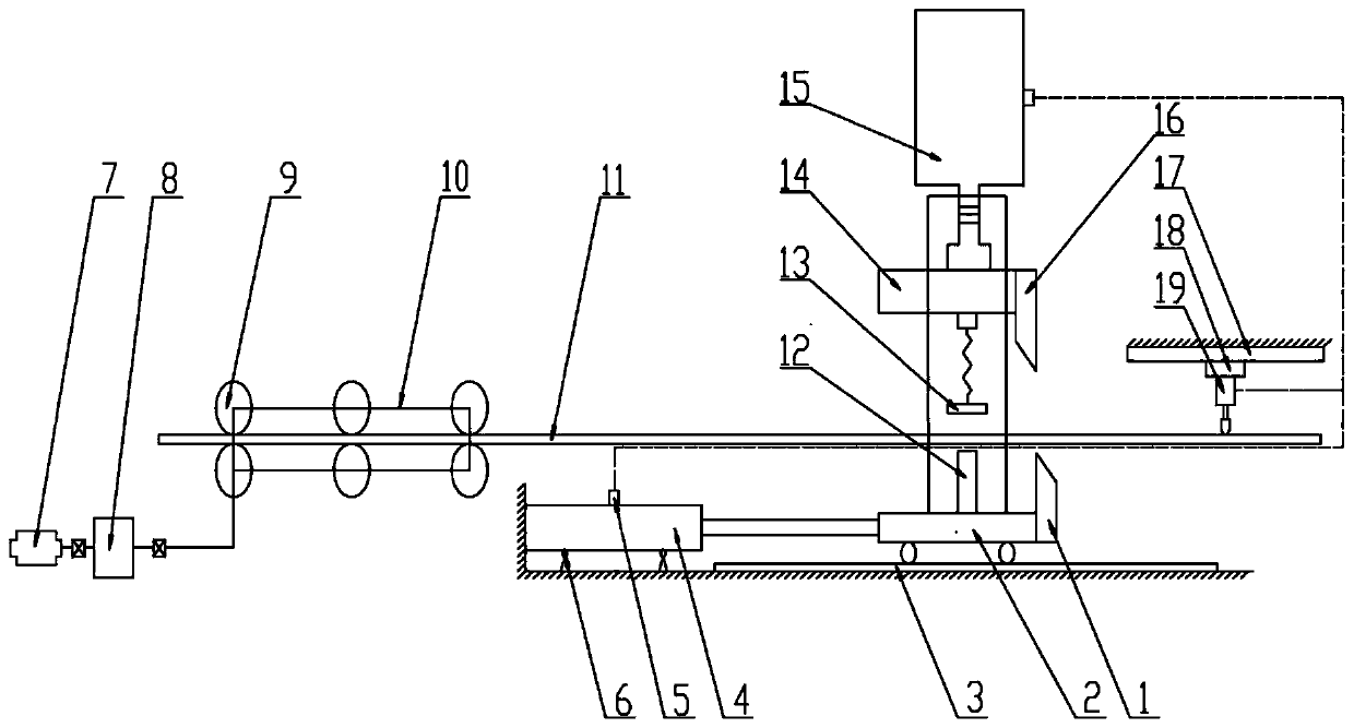
[0018] Such as Figure 1 to Figure 3 As shown, the present invention provides a flying shear, comprising a knife-carrying trolley 2, a lower knife block 1 and a bearing frame arranged on the knife-carrying trolley 2, used to control the knife-carrying trolley 2 to move along a first direction and make the The first actuator 4 whose speed is consistent with the feed speed of the workpiece, the moving tool rest 14, the second actuator 15 which is arranged on the carrier and is used to control the moving tool rest 14 to move in the vertical direction, The upper knife block 16 arranged on the movable...


PUM


Abstract

The invention discloses a flying shearing machine. The flying shearing machine comprises a tool-carrying trolley, a lower tool block, a carrier, a first actuator which is used for controlling the tool-carrying trolley to move in a first direction and making the speed of the tool-carrying trolley be consistent with the workpiece feeding speed, a mobile tool holder, a second actuator which is arranged on the carrier and used for controlling the mobile tool holder to move in the vertical direction, an upper tool block which is arranged on the mobile tool holder and located above the lower tool block, and a stroke monitoring mechanism for generating a shearing monitoring signal when detecting a workpiece, wherein the lower knife block and the carrier are arranged on the knife-carrying trolley;and the first direction is parallel to the length direction of workpieces. The flying shearing machine is stable in movement and can be automatically control, the position of the workpieces during the cutting process can be stabilized, the accurate cutting length of the workpieces is ensured, the productivity is high, and the product cutting quality is improved.

Description

technical field [0001] The invention belongs to the technical field of shearing equipment, in particular, the invention relates to a flying shear. Background technique [0002] Existing disc-type flying shears usually use rotating disc blades to continuously longitudinally shear the moving material mechanism. Disc flying shears are usually used to cut narrow-edged steel or remove edge burrs. The most important feature is the paired disc shears. Since the total tension of the steel has a great influence on the disc shear blade during shearing, it is easy to cause the problem of deviation in shearing, resulting in irregular shearing and easy loss. If the deviation is too serious, the shearing cannot be carried out, thus damage the equipment. In power shearing, both the shearing force and the rotating force of the cutter shaft are provided by the motor, and the force in the process of drawing and shearing is transmitted by the unit through the strip steel. The time is much l...

Claims


Application Information

Patent Timeline
Patent Type & Authority Applications(China)
IPC IPC(8): B23D25/02B23D33/02
CPCB23D25/02B23D33/02
Inventor 王波孙耀张元洲黄雯雯屈一鸣
Owner ANHUI POLYTECHNIC UNIV MECHANICAL & ELECTRICAL COLLEGE
Why Eureka
Try Eureka