Anti-drop pen
An anti-drop pen and refill technology, applied in printing, writing utensils, writing parts, etc., can solve the problem that pens cannot be automatically anti-drop, and achieve the effects of stable structure, convenient use and fast operation.
- Summary
- Abstract
- Description
- Claims
- Application Information
AI Technical Summary
Problems solved by technology
Method used
Image

Examples
Embodiment 1
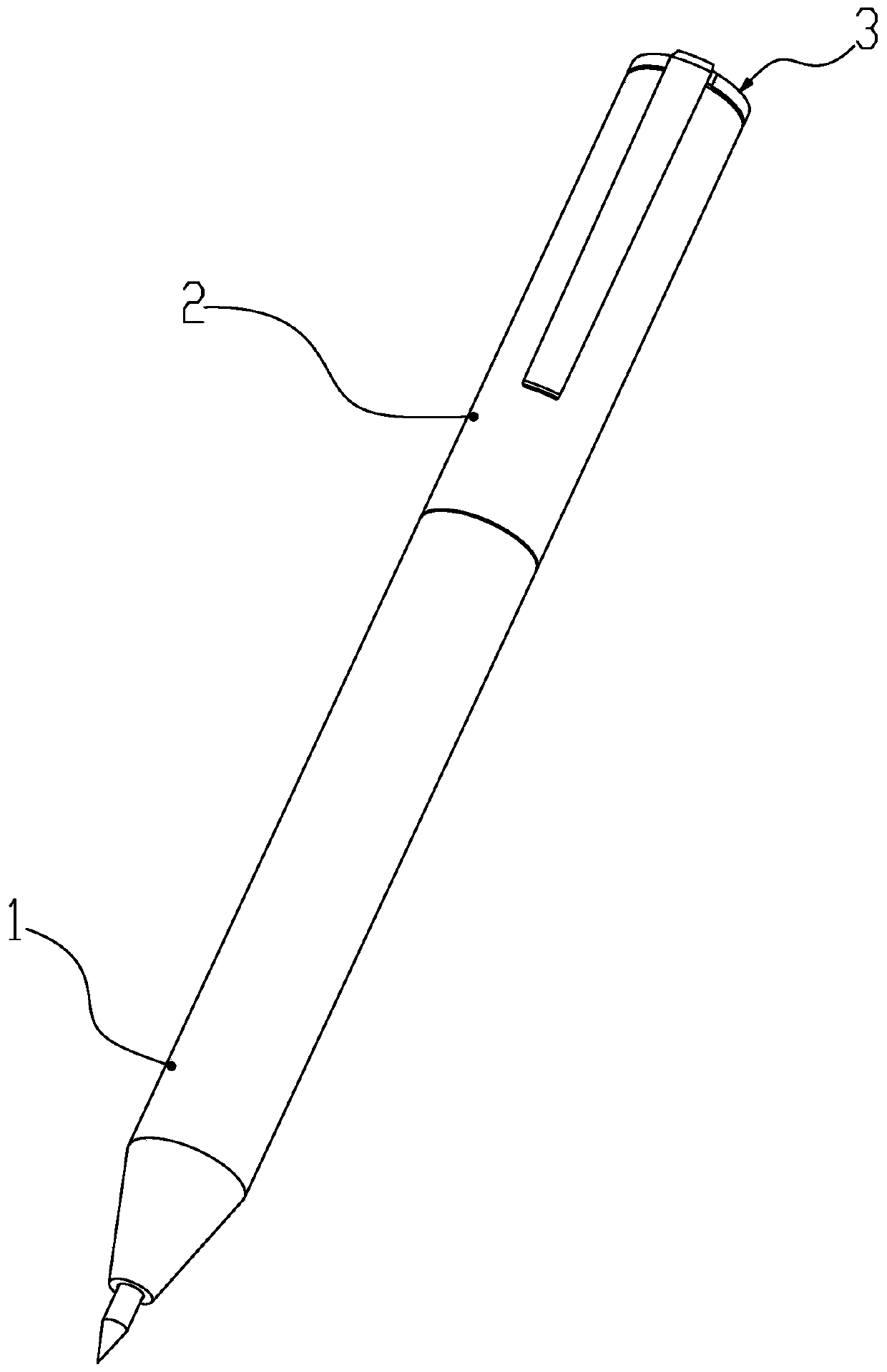
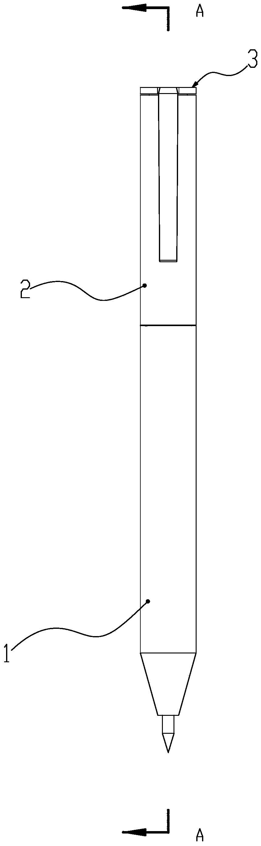
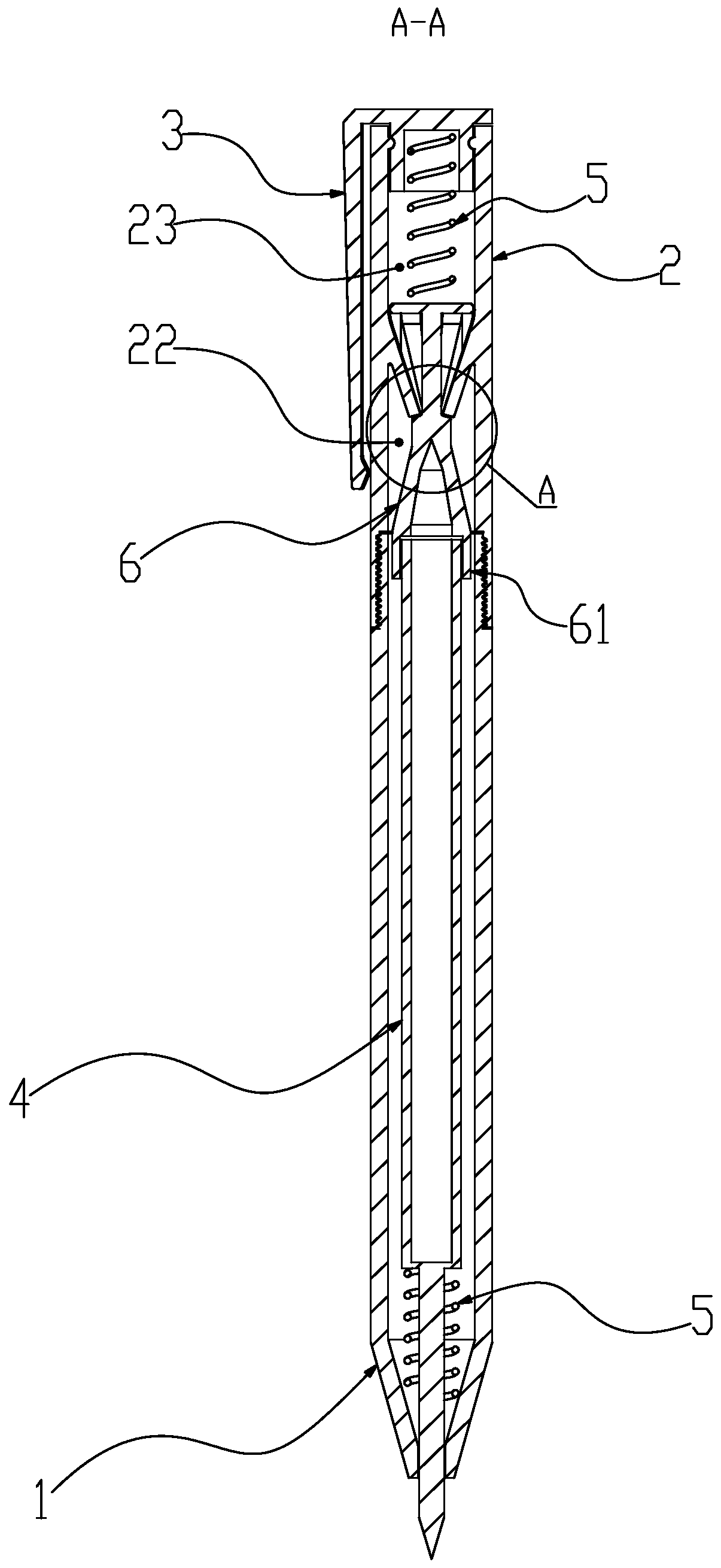
[0070] like Figures 1 to 5 A kind of drop-proof pen shown, comprises a pen holder 1, a support tail cylinder 2, an adjustment inner rod 6, a return spring 5, a writing core 4 and a pressing sleeve 3; the above-mentioned support tail cylinder 2 is a hollow inner cylinder structure, and its front and rear The inner space of the support tube 2 is bounded by the supporting and fixing rods 21, and is divided into the use cavity 22 and the stationary rod 21. Cavity 23; the above-mentioned adjusting inner rod 6 is a rod body structure, and the front end is provided with an adjusting ring platform 62, and the other end is provided with an abutting table 63; Inside, the tail end passes through the support tail cylinder 2, and forms a fit with the pressing sleeve 3 by means of threads or snaps; the above-mentioned adjusting inner rod 3 is movable and retractable in the support tail cylinder 2; the above-mentioned adjusting ring platform 62 is close to the tail end side. A support guid...
Embodiment 2
[0084] like Figures 6~9The anti-drop pen shown includes a pen holder 1, a supporting tail barrel 2, an adjusting inner rod 6, a return spring 5, a pen core 4 and a pressing sleeve 3; the supporting tail barrel 2 is a hollow inner barrel structure, and its front and rear It runs through and communicates, and the middle part of the barrel extends obliquely toward the axis of the support tailpiece 2, and is provided with one or more support fixing rods 21. The inner space of the above-mentioned support tailpiece 2 is bounded by the support fixing rods 21, and is divided into a use chamber 22 and a resting chamber. Cavity 23; the above-mentioned adjustment inner rod 6 is a rod body structure, the front end is provided with an adjustment ring platform 62, and the other end is provided with a collision platform 63; Inside, the tail end passes through the support tail barrel 2, and is formed to cooperate with the pressing sleeve 3 through threads or buckles; the above-mentioned adju...
PUM
 Abstract
Description
Claims
Application Information
 - Generate Ideas
- Intellectual Property
- Life Sciences
- Materials
- Tech Scout
- Unparalleled Data Quality
- Higher Quality Content
- 60% Fewer Hallucinations
Browse by: Latest US Patents, China's latest patents, Technical Efficacy Thesaurus, Application Domain, Technology Topic, Popular Technical Reports.
© 2025 PatSnap. All rights reserved.Legal|Privacy policy|Modern Slavery Act Transparency Statement|Sitemap|About US| Contact US: help@patsnap.com