Fuel distributor for internal combustion engines

A fuel distributor and fuel distribution technology, which are applied to fuel injection devices, special fuel injection devices, and adding non-fuel substances to fuel, can solve problems such as troublesome manufacturing of inserts, and achieve low-cost, simple manufacturing, and optimized geometry. Effect

Active Publication Date: 2019-11-26
ROBERT BOSCH GMBH
View PDF5 Cites 0 Cited by
  • Summary
  • Abstract
  • Description
  • Claims
  • Application Information

AI Technical Summary

Problems solved by technology

[0003] The fuel distributor strip known from DE 10 2014 205 179 A1 has the disadvantage that the insert must be produced in a complex manner, since it is designed as a thick-walled tube with grooves

Method used


Image

  • Fuel distributor for internal combustion engines
  • Fuel distributor for internal combustion engines
  • Fuel distributor for internal combustion engines

Examples


Embodiment Construction

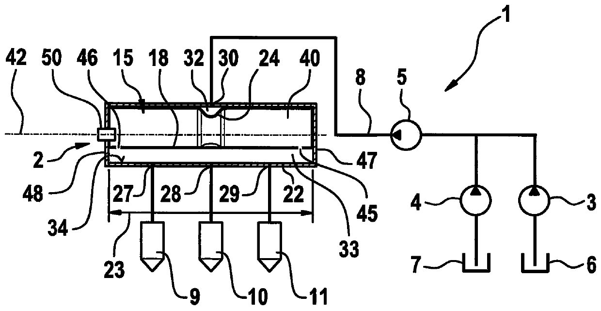
[0022] figure 1 A schematic illustration shows a fuel injection system 1 with a fuel distributor 2 according to a first exemplary embodiment of the invention, wherein the fuel distributor 2 is shown in a schematic sectional illustration. In this exemplary embodiment, fuel injection system 1 has a fuel pump 3 and a metering unit 4 designed as a backing pump 4 . Furthermore, a high-pressure pump 5 is provided. A fuel pump 3 delivers liquid fuel from a tank 6 to a high pressure pump 5 . The dosing unit 4 is used for temporarily dosing water from the storage container 7 into the delivered fuel. In this exemplary embodiment, the metering takes place upstream of the high-pressure pump 5 . In a variant, the metering can also take place at the high-pressure pump 5 . Depending on the operating state, liquid fuel or a mixture of liquid fuel and water is conveyed in line section 8 arranged between fuel distributor 2 and high-pressure pump 4 . Depending on the configuration, the wate...


PUM


Abstract

A fuel distributor (2), in particular a fuel distribution rail for mixture-compressing, spark-ignited internal combustion engines, includes a base body (22) at which at least one high-pressure input (30) and multiple high-pressure outputs (27-29) are provided and at least one insert element which is situated in the base body (22), the insert element (15) separating a distribution area which connects the high-pressure outputs (27-29) to one another at least essentially from a damping area (40). The insert element is configured at least essentially as a reshaped insert element (15). The insert element (15) forms a divider (18) which separates the distribution area (33) at least essentially from the damping area (40). Furthermore, a fuel injection system (1) including such a fuel distributor(2) is provided.

Description

technical field [0001] The invention relates to a fuel distributor, in particular a fuel distributor rail of an externally ignited internal combustion engine with compressed mixture, and to a fuel injection system having such a fuel distributor. In particular, the invention relates to the field of fuel injection systems for motor vehicles in which fuel is injected directly into the combustion chamber of an internal combustion engine. Background technique [0002] A fuel distribution rail for an internal combustion engine is known from DE 10 2014 205 179 A1. The known fuel distributor strip has an elongated housing with a cavity, the fuel distributor strip also has a fuel inlet opening into the cavity and at least two outlets exiting the cavity. Fuel outflow ports, for each fuel injector. In this case, a body is arranged in the cavity, which has a groove connecting the two fuel outlet openings to one another and in the region of the fuel inlet opening has a groove radially ...

Claims


Application Information

Patent Timeline
Patent Type & Authority Applications(China)
IPC IPC(8): F02M55/02F02M25/025
CPCF02M55/025F02M25/025F02M25/0221F02M2200/315F02M55/04F02D2041/389F02M63/0225F02M63/0275F02M2200/8053
Inventor O·杰伦特P·申克
Owner ROBERT BOSCH GMBH
Why Eureka
Try Eureka