Convenient-to-install street lamp based on new energy sources

A new energy and street lamp technology, which is applied to the parts of lighting devices, electric light sources, energy-saving lighting, etc., can solve the problems of inconvenient disassembly and transportation, achieve convenient installation work, increase connection strength, increase stability and The effect of support strength

Inactive Publication Date: 2019-11-26
金华市秸和环保技术咨询有限公司
View PDF3 Cites 1 Cited by
  • Summary
  • Abstract
  • Description
  • Claims
  • Application Information

AI Technical Summary

Problems solved by technology

There are always some deficiencies in the installation process of existing new energy street lamps. The structure between the lamp post and the base of the existing street lamps is integrated, which is inconvenient for disassembly and transportation

Method used


Image

  • Convenient-to-install street lamp based on new energy sources
  • Convenient-to-install street lamp based on new energy sources
  • Convenient-to-install street lamp based on new energy sources

Examples


Embodiment 1

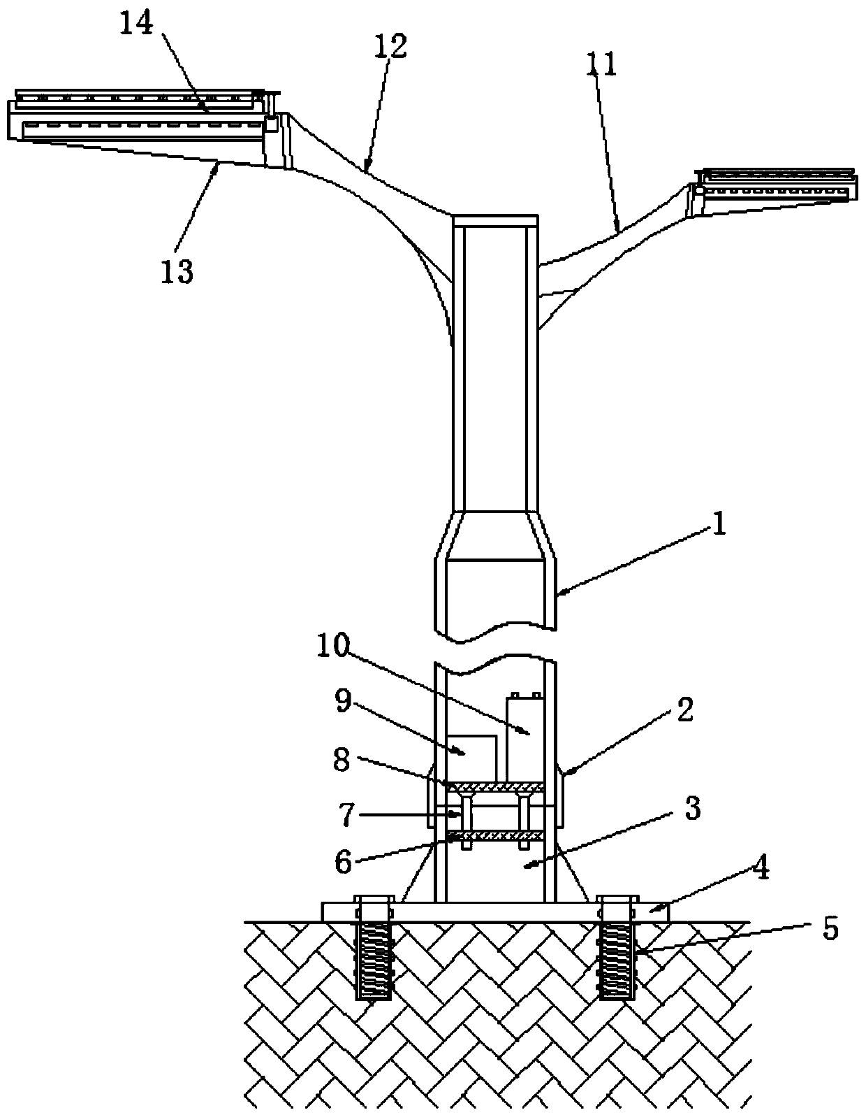
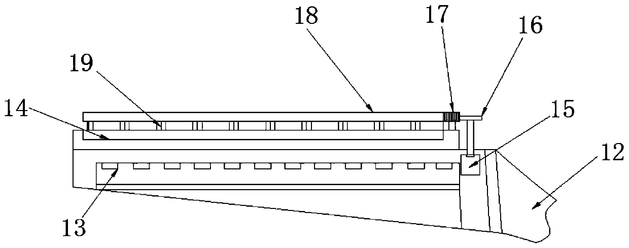
[0026] refer to Figure 1-3 , an easy-to-install street lamp based on new energy, including a lamp post 1, a base is provided at the bottom of the lamp post 1, and the base includes a base plate 4, and a fixed tube 3 is fixed on the top of the base plate 4, and the fixed tube 3 and the lamp post 1 The same rotating sleeve 2 is threaded on the joint, and the lamp post 1 and the fixed tube 3 are respectively fixed with a fixed plate 8 and a limit plate 6, and a plurality of limit columns 7 are fixed at the bottom of the fixed plate 8. 7 is movably inserted on the limit plate 6, and the top of the lamp post 1 is respectively fixed with an auxiliary light frame 11 and a main light frame 12, and the auxiliary light frame 11 and the main light frame 12 are fixed with an auxiliary light and a main light 13, and the auxiliary light and Photovoltaic panels 14 are fixed on the tops of the main lamps 13 .

[0027] The top of the fixed plate 8 is respectively provided with a storage batt...

Embodiment 2

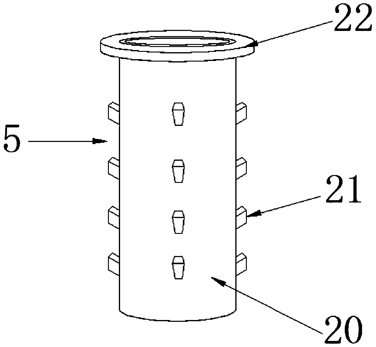
[0030] refer to Figure 4 , an easy-to-install street lamp based on new energy sources. The difference between this embodiment and Embodiment 1 is that an annular groove is formed on the inner wall of the positioning hole 23, and a rubber ring 24 is embedded in the annular groove.

[0031] The working principle of this embodiment: the rubber ring 24 can increase the tightness of the bolt and the inner wall of the positioning hole 23, prevent rainwater from entering the limiting tube 20 from the positioning hole 23, improve the sealing of the joint between the limiting mechanism 5 and the base plate 4, and increase durability of the device.


PUM


Abstract

The invention discloses a convenient-to-install street lamp based on new energy sources. The convenient-to-install street lamp comprises a lamp post, wherein a base is arranged at the bottom end of the lamp post; the base comprises a case plate; a fixing pipe is fixed at the top of the base plate; the same rotating sleeve is connected in a sleeving way onto a connecting position of the fixing pipeand the lamp post through screw threads; a fixing plate is fixed inside the lamp post; a position limiting plate is fixed inside the fixing pipe; a plurality of position limiting posts are fixed at the bottom of the fixing plate; the position limiting posts are movably inserted and connected onto the position limiting plate; a sub lamp frame and a main lamp frame are respectively fixed at the topend of the lamp post; a sub lamp is fixed on the sub lamp frame; a main lamp is fixed on the main lamp frame; and a photovoltaic panel is fixed at the top end of each of the sub lamp and the main lamp. The convenient-to-install street lamp has the advantages that the sealing and fixing work can be performed at a seam part between the lamp post and the fixing pipe; the position limiting posts arranged at the bottom of the fixing plate arranged in the lamp post can be inserted and connected onto the position limiting plate; the positioning work before device installation is realized; and the device installation work is convenient.

Description

technical field [0001] The invention relates to the technical field of street lights, in particular to an easy-to-install street light based on new energy sources. Background technique [0002] With the continuous development of urbanization in our country, the population gradually gathers in large and medium-sized cities, and the built-up area of ​​urban areas is also expanding. Subsequently, more and more roads were built in urban areas. A large number of street lights need to be installed on both sides of the road in the urban area. A large number of street lamps require a large amount of power supply when they are illuminated at night. In our country, electricity is mainly generated by fire or water, and the power supply is tense. At the same time, to transmit electricity to street lamps, a large number of transmission lines and transformation equipment need to be laid, which is costly. [0003] In the prior art, street lamps using new energy sources for power genera...

Claims


Application Information

Patent Timeline
IPC IPC(8): F21S9/03F21V17/12F21V23/00F21V23/04F21V23/06F21V31/00H02S40/10F21W131/103
CPCF21S9/035F21V17/12F21V23/00F21V23/04F21V23/06F21V31/005F21W2131/103H02S40/10Y02B20/72Y02E10/50
Inventor 罗志诚
Owner 金华市秸和环保技术咨询有限公司
Why Eureka
Try Eureka