Cold beam with two coiled tubes

A chilled beam and coil technology, which is applied to the chilled beam field equipped with two coils, can solve the problems of poor circulating air processing capacity and general cooling effect, achieve good cooling effect and circulating air capacity, improve processing capacity, increase Effect of coil area

Pending Publication Date: 2019-11-26
KUNSHAN KLIMASYSTTECHN
View PDF1 Cites 0 Cited by
  • Summary
  • Abstract
  • Description
  • Claims
  • Application Information

AI Technical Summary

Problems solved by technology

At present, the common chilled beam is that the heat exchanger is installed in parallel under the ceiling. The return air in the room is sucked by the low pressure caused by the fresh air injection and then sent out through the heat exchanger. For example, the invention patent of application number CN201711260128.1 is an active chilled beam. And the chilled beam air conditioning system, including a shell, the bottom of the shell is provided with an air inlet, the two sides of the shell are provided with an air outlet, the inside of the shell is provided with an air outlet pipe and a heat exchange coil connected with the air outlet, and the air outlet is provided with There is a rotatable air guide vane, which can control the wind direction through the air guide vane, but the chilled beam uses a single heat exchange coil, the cooling effect is average, and the handling capacity of the circulating air is poor

Method used


Image

  • Cold beam with two coiled tubes

Examples


Embodiment Construction

[0015] The present invention will be described in further detail below in conjunction with the accompanying drawings.

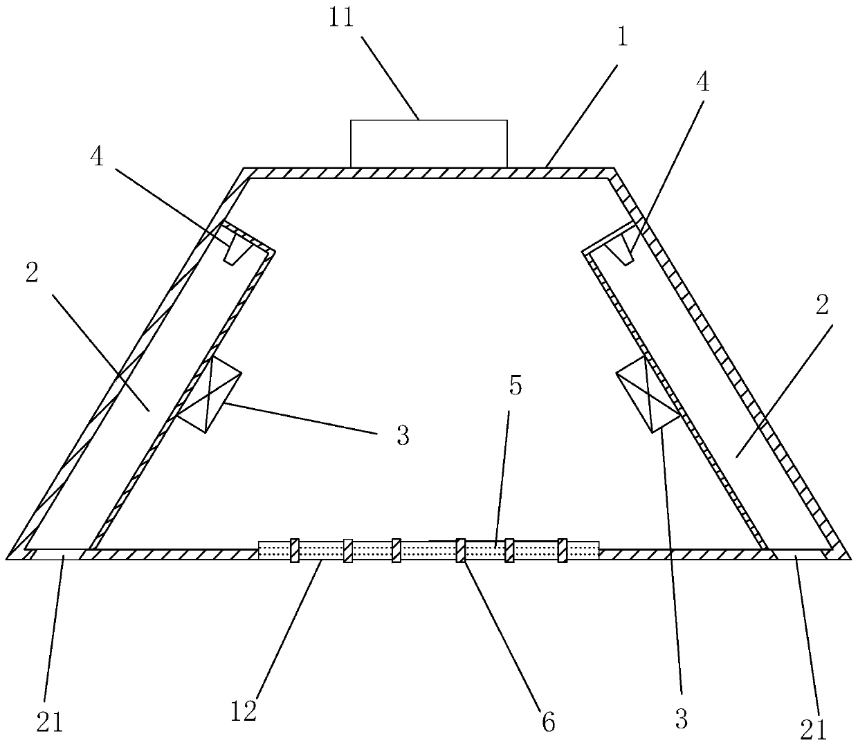
[0016] A chilled beam with two coils, see figure 1 , which includes a housing 1, the cross section of the housing 1 is a positive trapezoid, the bottom of the housing 1 is provided with an air return port 12, the two inner walls of the housing 1 are provided with an air outlet duct 2 along the length direction of the housing 1, and the air outlet The air duct 2 is parallel to the corresponding side of the housing 1, the bottom surface of the air outlet duct 2 is provided with an air outlet 21 along its length direction, and the inner sidewall of the air outlet duct 2 is symmetrically arranged with a channel connected to the air outlet duct 2 along its length direction. The heat exchange coil 3 is provided with a nozzle 4 on the top surface of the air outlet pipe 2 near the fresh air inlet 11 to introduce fresh air into the air outlet pipe 2 .

[0017] The to...


PUM


Abstract

The invention discloses a cold beam with coiled tubes. The cold beam comprises a housing, wherein the cross section of the housing is in the shape of a trapezoid; an air return hole is formed in the bottom of the housing; two inner side walls of the housing are equipped with air outlet pipelines parallel to the side surface of the housing in a length direction of the housing; the bottom surfaces of the air outlet pipelines are equipped with air outlets in a length direction of the air outlet pipelines; the inner side walls of the air outlet pipelines are symmetrically equipped with one heat exchange coiled tube which communicates with the air outlet pipelines separately; and top surfaces, close to fresh air inlets, of the air outlet pipelines are equipped with spray nozzles for guiding fresh air into the air outlet pipelines. According to the technical scheme adopted by the invention, the key point is that the two heat exchange coiled tubes can be adopted to increase coiled tube area,and improves processing ability of circulating air; and fresh air is sprayed in from the spray nozzle after entering the housing to cause low-pressure of the air outlet pipelines, so that indoor circulating air is sucked in from the air return hole, and is mixed with fresh air for being fed into the room after being treated through the heat exchange coiled tubes, and mixed air is blown out from the two sides below the housing, and therefore, better refrigerating effect and air circulating ability are achieved.

Description

technical field [0001] The present invention relates to the technical field of air conditioning equipment, and more specifically, it relates to a chilled beam equipped with two coils. Background technique [0002] Chilled beam is a kind of cooling and heating equipment that has gradually emerged in recent years. Because the elongated shell is installed on the ceiling, it looks like a beam of a building from the outside, so it is called chilled beam. Generally used as a local air conditioner. At present, the common chilled beam is that the heat exchanger is installed in parallel under the ceiling. The return air in the room is sucked by the low pressure caused by the fresh air injection and then sent out through the heat exchanger. For example, the invention patent of application number CN201711260128.1 is an active chilled beam. And the chilled beam air conditioning system, including a shell, the bottom of the shell is provided with an air inlet, the two sides of the shell ...

Claims


Application Information

Patent Timeline
Patent Type & Authority Applications(China)
IPC IPC(8): F24F1/0047F24F1/0014F24F1/0059F24F1/0073F24F13/30F24F13/28
CPCF24F1/0014F24F1/0047F24F1/0059F24F1/0073F24F13/28F24F13/30
Inventor 于英娜
Owner KUNSHAN KLIMASYSTTECHN
Why Eureka
Try Eureka