
Deep hole blasting charging method for passing through solution cavity and solution cavity detecting device

A deep-hole blasting and detection device technology, which is applied in blasting and other directions, can solve the problems of pressure reduction, difficulty in charging PVC pipes, and complicated charging process, etc., and achieve the effects of reliable detonation, avoiding the leakage of explosive energy, and convenient construction

Active Publication Date: 2019-11-26
CHINA TIESIJU CIVIL ENG GRP CO LTD +1
View PDF4 Cites 6 Cited by
  • Summary
  • Abstract
  • Description
  • Claims
  • Application Information

AI Technical Summary

Problems solved by technology

This method can improve the blasting effect to a certain extent, but the charging process is complicated, and it is very difficult to charge the PVC pipe; at the same time, in order to avoid the gap between the explosives and cause the explosion rejection, it is necessary to arrange multiple priming charges, and the existence of caves The volume of the explosive gas will expand rapidly, resulting in a significant reduction in its pressure; obviously, the use of PVC pipes in the prior art has not effectively solved related problems

Method used


Image

  • Deep hole blasting charging method for passing through solution cavity and solution cavity detecting device
  • Deep hole blasting charging method for passing through solution cavity and solution cavity detecting device

Examples


Embodiment Construction

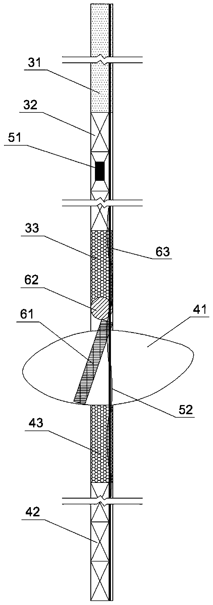
[0037] In this embodiment, the deep hole includes an upper section blasthole and a lower section blasthole, and there is a middle dissolution cavity between the upper section blasthole and the lower section blasthole, and the position and depth of the middle dissolution cavity are obtained by deep surveying.

[0038] see figure 1 , the charging method of the deep hole blasting through the dissolved cavity in this embodiment is:

[0039] In the upper section of the blasthole, from the upper section of the blasthole to the bottom of the upper section of the blasthole, there are successively the hole plugging section 31, the upper section of explosives 32 and the upper section of the dissolution cavity plugging section 33; The section is filled with lower explosives 42, and from the top surface of the lower explosives 42 to the bottom surface of the middle dissolution cavity 41, the lower block section 43 of the lower dissolution cavity is set to block the opening of the lower bl...


PUM

PropertyMeasurementUnit
Lengthaaaaaaaaaa

Abstract

The invention discloses a deep hole blasting charging method for passing through a solution cavity and a solution cavity detecting device. A deep hole comprises an upper blast hole section and a lowerblast hole section. A middle solution cavity exists between the upper blast hole section and the lower blast hole section, and the position and depth of the middle solution cavity are obtained through detection. In the upper blast hole section, a hole opening blocking section, upper section explosives and a solution cavity upper section blocking section are sequentially arranged from a hole opening to the hole bottom. In the lower blast hole section, the lower half section is filled with lower section explosives, and the upper half section is the solution lower section blocking section and blocks a hole opening of the lower blast hole section. A detonating cord communicates between the upper section explosives and the lower section explosives. According to the deep hole blasting chargingmethod, the blocking structure close to the middle solution cavity is utilized for carrying out delaying explosion to cause gas expansion, gas is extruded into the solution cavity to fill the solutioncavity after the upper section explosives and the lower section explosives are exploded, explosive energy leakage is effectively avoided, and the rock breakage effect is improved; and the remarkableadvantages of being convenient to construct, environment-friendly, efficient and economical are achieved.

Description

technical field [0001] The invention belongs to the technical field of engineering blasting, and more specifically relates to a charging method for deep hole blasting through a dissolved cavity and a detection device for a dissolved cavity, which are applied to rock mass blasting construction in a karst area. Background technique [0002] Karst refers to soluble rocks, especially carbonic acid rocks, such as limestone and gypsum, which are formed by the dissolution of flowing water containing carbon dioxide, and often have peculiar shapes, such as caves, stone ditches, stone forest caves, underground rivers, etc. . During the blasting operation of karst development, it is often encountered that the blast hole passes through the cave. The conventional charging method is difficult to ensure the continuity and uniformity of the blast hole charge in the lower section of the cave, resulting in a large number of roots and explosives after the blast. The energy is difficult to be ...

Claims


Application Information

Patent Timeline
IPC IPC(8): F42D1/08F42D3/04
CPCF42D1/08F42D3/04
Inventor 陈文尹李保文陈明董雪吴子文闫建斌杨康刘绍鑫
Owner CHINA TIESIJU CIVIL ENG GRP CO LTD
Learn More