
In-situ measurement planning method for high-steepness complex curved surface

A technology with complex curved surface and high steepness, applied in the field of curved surface measurement, can solve the problems of sparse measurement track and large longitudinal height difference

Active Publication Date: 2019-11-26
DALIAN UNIV OF TECH
View PDF11 Cites 8 Cited by
  • Summary
  • Abstract
  • Description
  • Claims
  • Application Information

AI Technical Summary

Problems solved by technology

In this method, the equal-illuminance angle is used as a constraint condition to generate non-equidistant transverse section contour lines, which solves the problem of sparse measurement trajectories near poles caused by large longitudinal height differences on high-steep surfaces.

Method used


Image

  • In-situ measurement planning method for high-steepness complex curved surface
  • In-situ measurement planning method for high-steepness complex curved surface
  • In-situ measurement planning method for high-steepness complex curved surface

Examples


Embodiment Construction

[0058] The specific implementation manner of the present invention will be described in detail in conjunction with the technical scheme and the accompanying drawings.

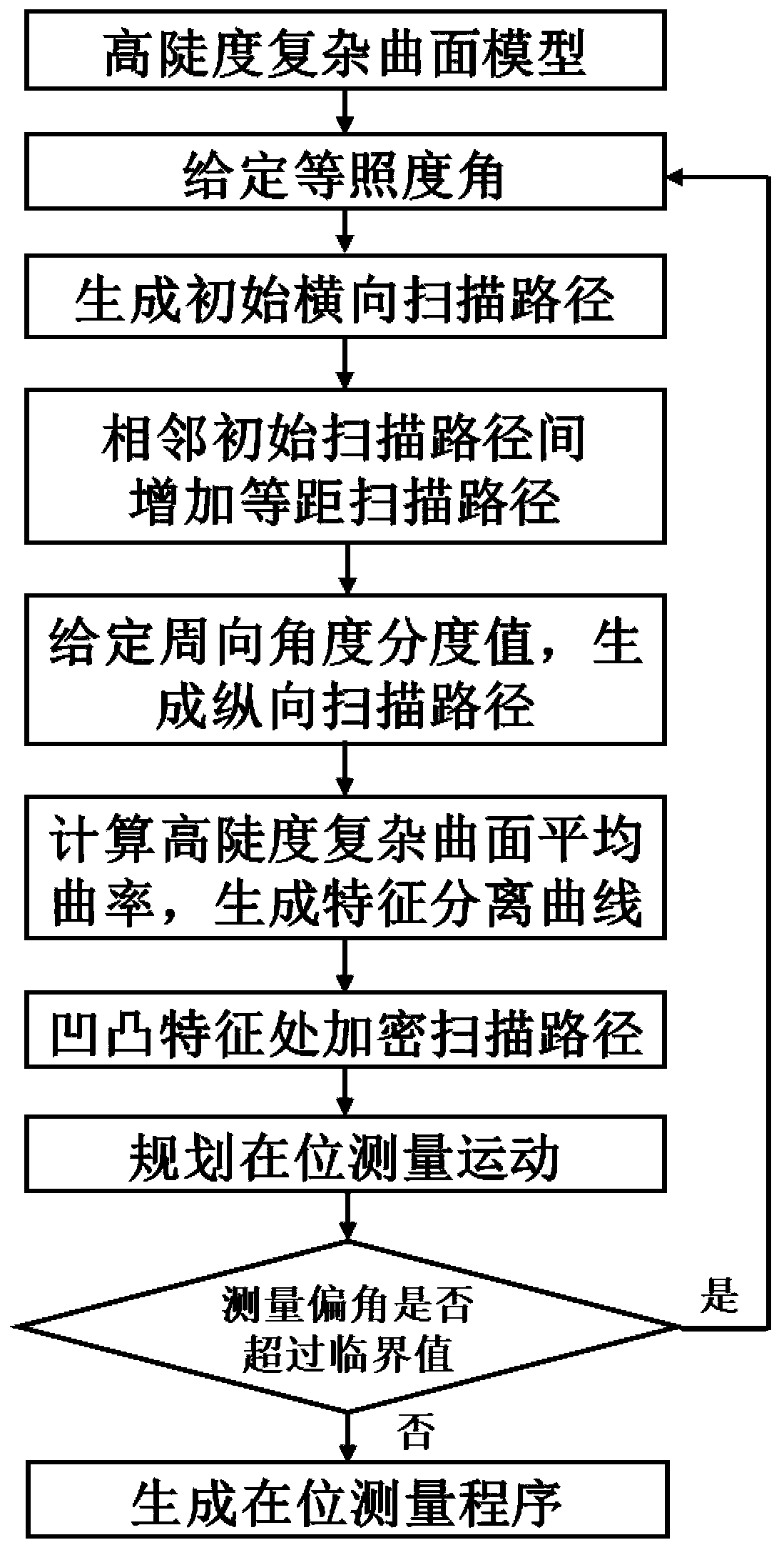
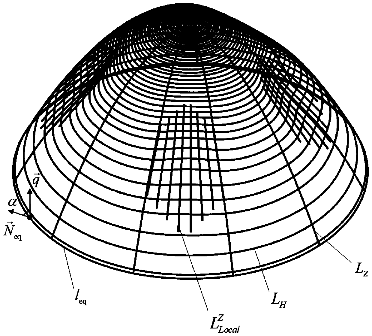
[0059] In this embodiment, the high-steep complex curved surface S used is a free-form surface with concave-convex undulations, a height of 52.5 mm, a diameter of 100 mm, and four non-rotationally symmetrical pits in the circumferential direction. attached figure 1 It is a flow chart of the planning method of the present invention, and the specific steps of the in-situ measurement planning of the curved surface are as follows:

[0060] Step 1 Generate an initial scan path

[0061] First, calculate the maximum steepness angle α of the containing aspheric surface A of the high-steep complex surface S, and the maximum steepness angle α is the edge section circle l of the mouth of the containing aspheric surface A eq The unit normal vector at any point on with the unit reference vector The included angle, the...


PUM


Abstract

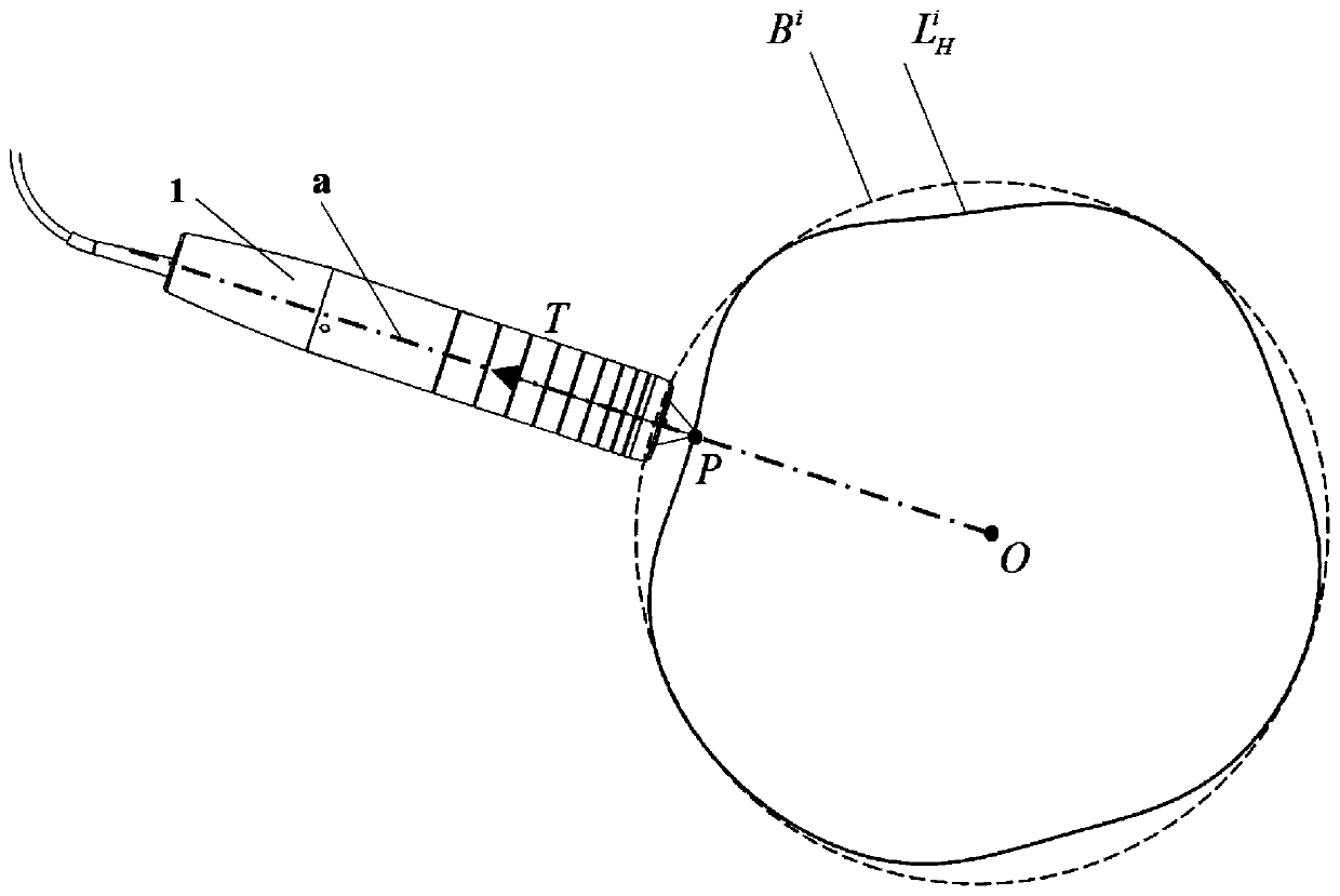
The invention discloses an in-situ measurement planning method for a high-steepness complex curved surface and belongs to the field of curved surface measurement. According to the method, the non-equidistant transverse section contour lines of a complex curved surface are generated with equiluminous angles adopted as constraint conditions; a full-surface latticed scanning measurement path is obtained based on the longitudinal section contour lines and non-equidistant transverse section contour lines of the complex curved surface; the concave-convex characteristics of the surface are extractedaccording to average curvature changes in two parameter directions, and local encryption scanning contour lines are generated; multi-section splicing measurement motion planning is carried out according to the equiluminous angles and the obtained scanning path, so that the movement trajectory of the reference point of a sensor is obtained; and finally, the measurement deflection angle of an optical measuring head is detected, so that the in-situ measurement planning of the complex curved surface is completed. With the method adopted, the in-place scanning path generation and measurement motionplanning of the high-steepness complex curved surface are achieved; the measurement precision of a characteristic area is guaranteed; and dynamic measurement errors caused by the multi-axis linkage of a machine tool are reduced. The method is reliable and high in universality.

Description

technical field [0001] The invention belongs to the field of curved surface measurement, in particular to an in-situ measurement planning method for high-steep complex curved surfaces. Background technique [0002] There is a large class of high-steep complex free-form surfaces in some high-end equipment, and the surface has concave-convex undulations. The guarantee of the machining contour accuracy of such curved surfaces needs to be based on the state obtained by in-situ precision measurement, and the processing error compensation adjustment should be carried out. The in-situ measurement process is based on the movement of the machine tool. According to the planned scanning path, the non-contact high-precision displacement sensor is used to obtain the surface data of the part, and then reflect the geometry of the complex surface. Therefore, reasonable planning of the scanning path and the measurement motion of the machine tool is an important guarantee to meet the require...

Claims


Application Information

Patent Timeline
IPC IPC(8): G01B11/24
CPCG01B11/24
Inventor 王永青袭萌萌刘海波李旭李特李佳伟薄其乐孟祥振隋延飞贾振元
Owner DALIAN UNIV OF TECH
Learn More