
Mthod for compensating temperature error of micro-electromechanical inertial measurement unit

An inertial measurement unit and temperature error technology, applied in the field of inertia, can solve the problems of not being able to truly describe the nonlinear characteristics of temperature error, failing to meet the requirements of compensation accuracy, easily falling into local optimal solutions, etc., to achieve the realization of nonlinear systems. Modeling, achieving accuracy, and accurately compensating the effect of temperature drift

Inactive Publication Date: 2019-11-26
BEIHANG UNIV
View PDF3 Cites 10 Cited by
  • Summary
  • Abstract
  • Description
  • Claims
  • Application Information

AI Technical Summary

Problems solved by technology

The polynomial model is simple and easy to implement. The temperature error is established as a polynomial linear combination of temperature by using the least square fitting method, which cannot truly describe the nonlinear characteristics of the temperature error, and only considers the temperature input information, which often fails to meet the compensation accuracy requirements; The BP neural network has outstanding learning ability, and it can fit the system model and input-output relationship through the known sample data training of the network, but it has the disadvantages of slow convergence speed and easy to fall into local optimal solution.

Method used


Image

  • Mthod for compensating temperature error of micro-electromechanical inertial measurement unit
  • Mthod for compensating temperature error of micro-electromechanical inertial measurement unit
  • Mthod for compensating temperature error of micro-electromechanical inertial measurement unit

Examples


Embodiment Construction

[0058] Exemplary embodiments of the present disclosure will be described in more detail below with reference to the accompanying drawings. Although exemplary embodiments of the present disclosure are shown in the drawings, it should be understood that the present disclosure may be embodied in various forms and should not be limited by the embodiments set forth herein. Rather, these embodiments are provided for more thorough understanding of the present disclosure and to fully convey the scope of the present disclosure to those skilled in the art.

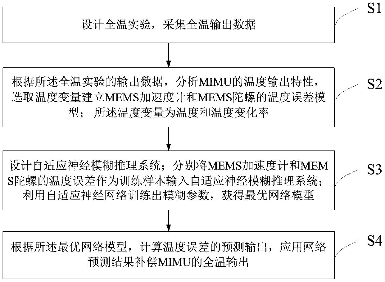
[0059] A method for temperature error compensation of micro-electromechanical inertial measurement units provided by an embodiment of the present invention, refer to figure 1 , the method includes:

[0060] S1. Design full-temperature experiments and collect full-temperature output data;

[0061] S2, according to the output data of described full temperature experiment, analyze the temperature output characteristic of MIMU, select...


PUM


Abstract

The invention discloses a method for compensating a temperature error of a micro-electromechanical inertial measurement unit. The method comprises the following steps: designing a full-temperature experiment and collecting full-temperature output data; according to the output data of the full-temperature experiment, analyzing the temperature output characteristics of the MIMU, and selecting temperature variables to establish a temperature error model of an MEMS accelerometer and an MEMS gyroscope; designing an adaptive neural fuzzy inference system; respectively inputting the temperature errors of the MEMS accelerometer and the MEMS gyroscope as training samples into the adaptive neural fuzzy inference system; carrying out trainingby using an adaptive neural network to obtain fuzzy parameters and an acquiringan optimal network model; and calculating prediction outputs of the temperature errors according to the optimal network model, and compensating the full-temperature output of the MIMU by applying a network prediction result. According to the method, a learning mechanism of the neural network enters fuzzy reasoning, so that the temperature error modeling precision is improved, the temperature drift of the MEMS gyroscope is accurately compensated, and the precision of the MIMU in a full-temperature range is realized.

Description

technical field [0001] The invention relates to the technical field of inertia, in particular to an MIMU temperature error compensation method using an adaptive neuro-fuzzy reasoning system. Background technique [0002] At present, as an important application in the field of inertial navigation, the inertial measurement unit (MIMU) based on micro-electromechanical systems has the advantages of small size, low cost, and mass production, and has opened up broad application prospects in strategic military and commercial civilian fields. MIMU, also known as Miniature Inertial Measurement Unit, (Miniature InertialMeasurementUnit, MIMU) is an important MEMS, which is composed of a miniature gyroscope, a miniature accelerometer, an application specific integrated circuit (ASIC), an embedded microcomputer and corresponding navigation software. Provide the position, speed and attitude information of the moving carrier. MEMS is also called Micro-Electro-Mechanical System (MEMS, Micr...

Claims


Application Information

Patent Timeline
Patent Type & Authority Applications(China)
IPC IPC(8): G01C21/16G01C21/20G06N5/04
CPCG01C21/16G01C21/20G06N5/048
Inventor 高爽张若愚蔡晓雯
Owner BEIHANG UNIV
Learn More