Amplifier with temperature compensation function

a technology of temperature compensation and amplifier, which is applied in the field of amplifiers, can solve the problems of affecting the stability affecting the operation of the overall system, and increasing the gain of such amplifiers or amplifier modules

Inactive Publication Date: 2000-03-28
MITSUBISHI ELECTRIC CORP
View PDF5 Cites 0 Cited by
  • Summary
  • Abstract
  • Description
  • Claims
  • Application Information

AI Technical Summary

Problems solved by technology

More particularly, the gain of such an amplifier or amplifier module tends to rise when the environmental temperature drops, and to drop when the environmental temperature rises.
The range of this change is particularly pronounced in multiple stage amplifiers, and in cases can interfere with stable operation of the overall system.
The distortion characteristic of such a power amplifier module thus deteriorates when the environmental temperature is low and gain is greatest.
Loss of power and efficiency are also potential problems when the environmental temperature is high and gain is low.
A drawback to the above-noted conventional temperature compensation circuit is that a separate external power supply is needed to supply the required bias voltage to the gain control terminal, that is, the gate of the amplification FET.
This complicates circuit design and configuration, and thus leads to increased cost.
Process control can be expected to become difficult, however, when FETs with significantly different characteristics are formed on a single wafer to achieve a power amplification apparatus as described above, with particular performance characteristics.
Conversely, a drop in the environmental temperature results in greater loss, and the high frequency signal level supplied to the first active device for amplification drops.

Method used


Image

  • Amplifier with temperature compensation function
  • Amplifier with temperature compensation function
  • Amplifier with temperature compensation function

Examples


embodiments 1 through 10

Preferred embodiments 1 through 10 of an amplifier with a temperature compensation function according to the present invention are described in detail below with reference to the accompanying figures.

embodiment 1

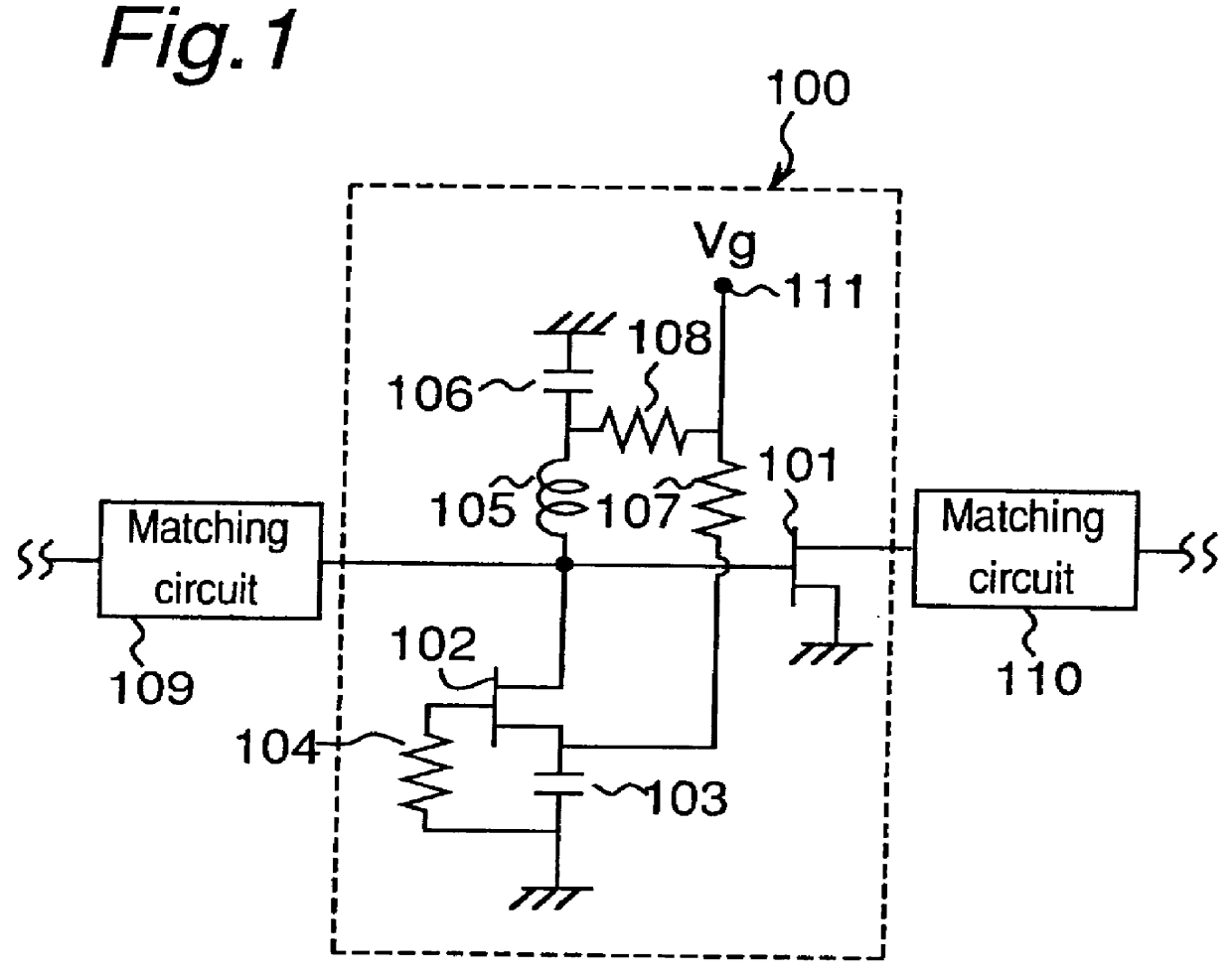
FIG. 1 is a circuit diagram of an amplifier 100 with a temperature compensation function according to a first embodiment of the present invention. A matching circuit 109 for converting the impedance of a high frequency power supply to an impedance appropriate for the amplifier 100 is provided before the amplifier 100. A further matching circuit 110 provided after the amplifier 100 matches the impedance of the amplified high frequency output from the amplifier 100 to the impedance of the downstream circuits.

The configuration of the amplifier 100 is described next.

As shown in FIG. 1, the amplifier 100 comprises a circuit for implementing a temperature compensation function connected in series with the gate of an active device 101 for signal amplification. A device such as an FET or HEMT is used as the active device 102 for temperature compensation and the active device 101 for amplification.

The circuit achieving the temperature compensation function comprises an inductor 105 and resis...

embodiment 2

An amplifier 120 with a temperature compensation function according to a second embodiment of the present invention is described next below with reference to FIG. 7, which is a circuit diagram thereof.

Note that like parts in an amplifier according to the present embodiment shown in this figure and the amplifier 100 shown in FIG. 1 are identified by like reference numbers, and further description thereof is omitted below.

As shown in FIG. 7, an amplifier 120 according to the present embodiment replaces resistor 104 in amplifier 100 according to the first embodiment with a resistor 112 connected between the gate of active device 102 for temperature compensation and the gate of active device 101 for amplification.

In this configuration the potential difference between the gate and source-drain electrodes of active device 102 is 0V irrespective of the drain current setting of active device 101. As a result, the resistance of active device 102 is constant. That is, high frequency signal lo...


PUM


Abstract

An amplifier with a temperature compensation function featuring a simple configuration wherein a high frequency signal attenuation circuit is connected to a gate terminal of an amplifying active device. The high frequency signal attenuation circuit uses the source terminal and the drain terminal of a compensating active device as input and output terminals, and the gate terminal is grounded.

Description

1. Field of the InventionThe present invention relates to an amplifier for amplifying signals in the microwave and milliwave frequency bands, and relates particularly to an amplifier having a function for compensating variations in amplifier gain resulting from changes in amplifier temperature.2. Description of the Prior ArtThe gain of microwave and milliwave amplifiers and amplifier modules comprising such amplifiers tends to vary with the environmental temperature in which the amplifier or amplifier module is used. More particularly, the gain of such an amplifier or amplifier module tends to rise when the environmental temperature drops, and to drop when the environmental temperature rises. The range of this change is particularly pronounced in multiple stage amplifiers, and in cases can interfere with stable operation of the overall system.For example, in a power amplifier module comprising three two-stage amplifier MMIC devices with different outputs in series, a 100.degree. C. ...

Claims


Application Information

Patent Timeline
Patent Type & Authority Patents(United States)
IPC IPC(8): H03F3/189H03F1/30H03F3/193H03F3/60H03H11/24
CPCH03F1/306H03F3/1935
Inventor CHAKI, SHINNAKAJIMA, YASUHARU
Owner MITSUBISHI ELECTRIC CORP
Why Eureka
Try Eureka