Method for operating a selective switching device for signals

Active Publication Date: 2017-06-22
TESAT SPACECOM
View PDF1 Cites 1 Cited by
  • Summary
  • Abstract
  • Description
  • Claims
  • Application Information

AI Technical Summary

Benefits of technology

[0006]There may be a need to enable simplifi

Problems solved by technology

The additional expenditure arising by application of the “hybrid temperature compensation techni

Method used


Image

  • Method for operating a selective switching device for signals
  • Method for operating a selective switching device for signals
  • Method for operating a selective switching device for signals

Examples


Embodiment Construction

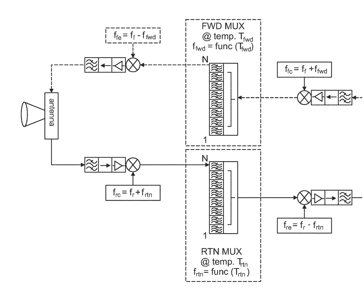
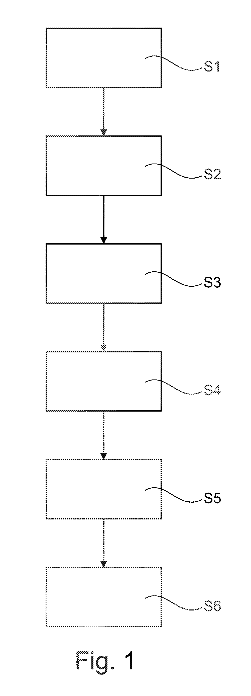
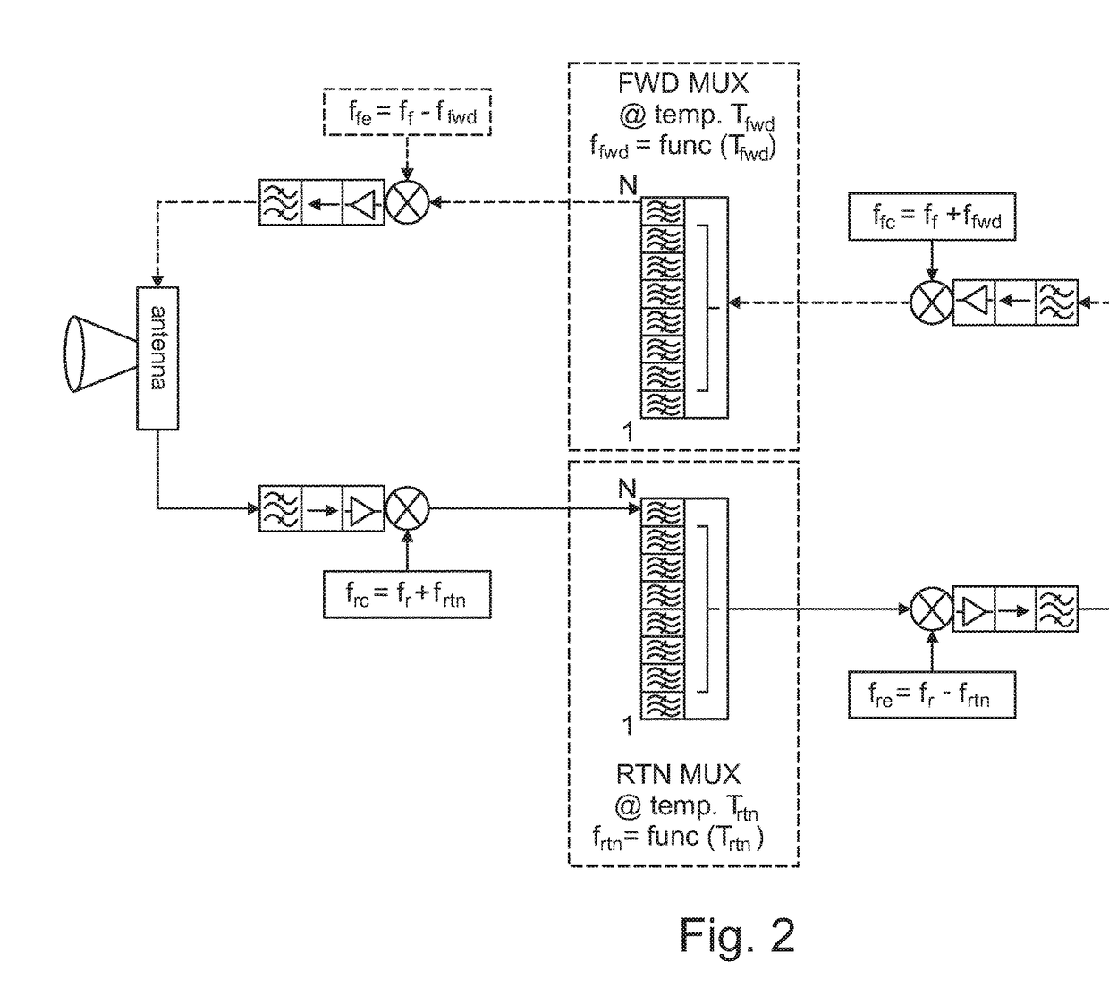
[0024]FIG. 1 shows a schematic view of an exemplary method for operating a selective switching device for signals. The method comprises the following steps, not necessarily in this order:

[0025]Step S1: determining a current temperature in the region of the selective switching device;

[0026]Step S2: determining a signal shift of the selective switching device due to the current temperature;

[0027]Step S3: adding the signal shift to an input signal of the selective switching device as to receive a compensated signal for which the signal shift due to the current temperature is compensated; and

[0028]Step S4: removing the signal shift from an output signal of the selective switching device as to receive a corrected signal for which the compensation is corrected.

[0029]Furthermore, the method for operating a selective switching device comprises the following optional steps, not necessarily in this order:

[0030]Step S5: determining a desired signal range of the input signal and / or of the outpu...


PUM


Abstract

The disclosure relates to a method for operating a selective switching device for signals, a related selective switching device, and a message transmission system having the selective switching device. An embodiment of the method includes the following steps, not necessarily in this order: determining a current temperature in the region of the selective switching device; determining a signal shift of the selective switching device due to the current temperature; adding the signal shift to an input signal of the selective switching device as to receive a compensated signal for which the signal shift due to the current temperature is compensated; and removing the signal shift from an output signal of the selective switching device as to receive a corrected signal for which the compensation is corrected.

Description

CROSS-REFERENCE TO RELATED APPLICATION[0001]This application claims priority to German patent application number 10 2015 016 462.7, filed Dec. 21, 2015, which is incorporated herein by reference in its entirety.TECHNICAL FIELD[0002]The disclosure relates to a method for operating a selective switching device for signals, such a selective switching device, and a message transmission system with such a selective switching device.BACKGROUND[0003]A waveguide filter is a passive filter used in microwave technology in the form of a specifically equipped waveguide. It serves to suppress or to let pass specific frequencies of the electromagnetic wave propagating in the waveguide. Among other things, waveguide filters may be used as an assembly for larger transmitter systems, radar systems, and for communication satellites.[0004]Huge fluctuations in temperature may occur particularly in aerospace applications, which fluctuations in temperature may become effective as intense changes of the v...

Claims


Application Information

Patent Timeline
IPC IPC(8): H03H7/46H03H7/01H03H11/04H03H11/34H03H17/02
CPCH03H7/46H03H11/34H03H7/0138H03H11/04H03H17/0201H03D7/161H03J3/04H04B1/40
Inventor AUER, ERICH
Owner TESAT SPACECOM
Why Eureka
Try Eureka