Capacitive coupling structure and dielectric filter applying same

A dielectric filter and capacitive coupling technology, applied in waveguide-type devices, circuits, electrical components, etc., can solve problems such as inconvenience in debugging, and achieve the effect of large adjustable range of coupling coefficient, wide technical application range, and convenient later debugging.

Pending Publication Date: 2019-11-26
JIANGSU JIANGJIA ELECTRONICS +1
View PDF0 Cites 11 Cited by
  • Summary
  • Abstract
  • Description
  • Claims
  • Application Information

AI Technical Summary

Problems solved by technology

Because its depth is too large, it will cause inconvenience in later debugging

Method used


Image

  • Capacitive coupling structure and dielectric filter applying same
  • Capacitive coupling structure and dielectric filter applying same
  • Capacitive coupling structure and dielectric filter applying same

Examples


Embodiment Construction

[0026] The present invention is described in further detail below in conjunction with the accompanying drawings, to better understand the technical solutions and related mechanisms of the present invention:

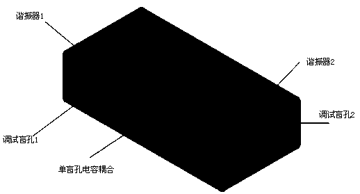
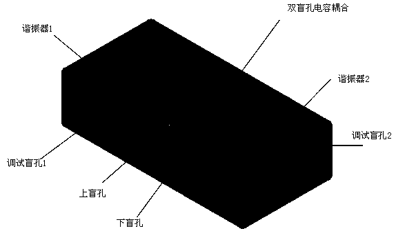
[0027] The present invention proposes a capacitive coupling structure with double blind holes, such as image 3 and Figure 4 Shown (the first implementation of capacitive coupling). Each dielectric resonator includes a body made of solid dielectric material and a debugging hole located on the surface of the body. The debugging hole is a blind hole for debugging the resonant frequency of the dielectric resonator where it is located. At least a pair of opposite negative coupling holes in the form of a blind hole structure are introduced between the two surface-metallized dielectric resonators 1 and 2, ie upper blind holes and lower blind holes (referred to as double blind holes). The upper blind hole is located on the surface where the two debugging blind holes 1 and 2 a...


PUM


Abstract

The invention relates to a capacitive coupling structure and a dielectric filter applying the capacitive coupling structure. The capacitive coupling structure is arranged on at least two dielectric resonators, every two dielectric resonators are set as one unit; a debugging hole is respectively formed in bodies of the two dielectric resonators on the same unit, and the debugging holes are blind holes; and the following structure is also formed, namely at least one negative coupling hole is respectively formed in the upper surface and the lower surface of a body at a connection position of thetwo adjacent dielectric resonators, the negative coupling holes are blind holes, and each negative coupling hole is not deeper than the debugging holes. The capacitive coupling structure provided by the invention has a wider adjustable coupling coefficient range by virtue of reasonable arrangement of the debugging holes and the negative coupling holes, a technical application range can be wider, and later-period debugging can be facilitated, so that the capacitive coupling structure provided by the invention has a good market application prospect.

Description

technical field [0001] The invention relates to a capacitive coupling structure and a dielectric filter using the structure, and relates to the technical field of communication equipment. Background technique [0002] With the increasing development of mobile communication technology, dielectric filters have gradually attracted people's attention due to their advantages of miniaturization, light weight, and low loss. The dielectric filter is realized by metallizing the surface of an integrally formed high dielectric constant dielectric ceramic structure, without the need for a metal cavity, and its volume and weight are much smaller than the above two filters. In addition, due to the high Q value of the dielectric ceramic material and good temperature drift characteristics, the dielectric filter also maintains advantages in terms of filter performance such as loss and operating frequency stability. Therefore, dielectric filters have become the mainstream choice for future m...

Claims


Application Information

Patent Timeline
Patent Type & Authority Applications(China)
IPC IPC(8): H01P1/20
CPCH01P1/2002
Inventor 陈建新严格秦伟严盛喜杨安岗汪玮玺王猛赵俊
Owner JIANGSU JIANGJIA ELECTRONICS
Why Eureka
Try Eureka