Proportional valves for controlling gaseous media

A gaseous medium and proportional valve technology, applied in the field of proportional valves, can solve the problems of large structural space and low-efficiency structural form of proportional valves, and achieve the effect of optimized orientation

Active Publication Date: 2022-05-24
ROBERT BOSCH GMBH
View PDF6 Cites 0 Cited by
  • Summary
  • Abstract
  • Description
  • Claims
  • Application Information

AI Technical Summary

Problems solved by technology

This can lead to greater installation space and thus to an inefficient design of the entire proportional valve

Method used


Image

  • Proportional valves for controlling gaseous media
  • Proportional valves for controlling gaseous media

Examples


Embodiment Construction

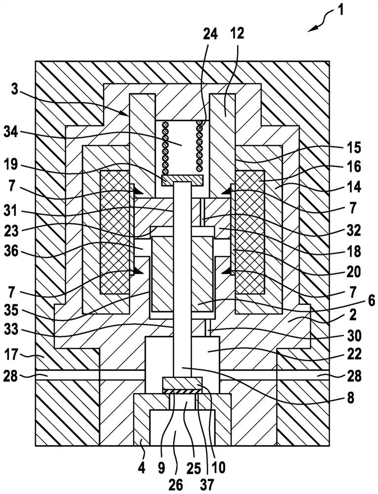
[0019] Figure 1 To illustrate an embodiment of the proportional valve 1 according to the present invention in longitudinal section. Proportional valve 1 has a valve housing 2, the valve housing having an inner chamber 3. In the inner chamber 3 is arranged an electromagnetic coil 16 having an outer pole 14 and an inner pole 15. The inner pole 15 includes a first inner electrode element 12 and a second inner electrode element 18. The first inner pole element 12 and the second inner pole element 18 are connected to each other by weld 7.

[0020] Valve housing 2, the first inner pole element 12 and the second inner pole element 18 limiting spring chamber 34, wherein the spring chamber 34 is constructed as part of the inner chamber 3. In the spring chamber 34 is arranged a closing spring 24, the closing spring 24 is supported on one side on the valve housing 2 and the other side is supported on the disc terminal 19 of the connecting element 8 arranged in the inner chamber 3. The conne...


PUM


Abstract

The invention relates to a proportional valve (1) for controlling a gaseous medium, in particular hydrogen, having a valve housing (2), wherein an inner chamber (3) is formed in the valve housing (2). An electromagnetic coil (16) having an outer pole (14) and an inner pole (15) is arranged in the inner chamber (3). Furthermore, the inner pole (15) is designed in two parts and comprises a first inner pole element (12) and a second inner pole element (18).

Description

Technical field [0001] The present invention relates to a proportional valve for controlling a gaseous medium, in particular hydrogen, for example, used in a vehicle having a fuel cell drive device. Background [0002] In the field of vehicle development, gaseous fuels, especially hydrogen, are alternatives to conventional liquid fuels. In vehicles having a fuel cell as a drive device here it is necessary to control the hydrogen gas flow, wherein the gas flow is not controlled as non-continuously as when injecting liquid fuel, but for example, the use of a proportional valve, the proportional valve according to the desired driving power to adjust the opening cross section. [0003] Known by DE 10 2012 204 565 is a proportional valve for controlling gaseous media. The proportional valve comprises a nozzle body having a through opening, a closing element with an elastic element. By closing the element it is possible to release and close the penetration opening on the valve seat. Th...

Claims


Application Information

Patent Timeline
Patent Type & Authority Patents(China)
IPC IPC(8): F16K1/52F16K27/02F16K31/06
CPCF16K1/523F16K27/029F16K31/0655F16K31/0675F16K31/0693
Inventor A·格林贝格尔J·韦斯内尔H-C·马格尔
Owner ROBERT BOSCH GMBH
Why Eureka
Try Eureka