Implants for hair transplantation

A technology of hair transplantation and planter, which is applied in the fields of medical science and surgery, and can solve problems such as damage to the site to be planted, blood outflow from the wound, and blood affecting the doctor's sight.

Active Publication Date: 2020-10-30
THE FIRST AFFILIATED HOSPITAL OF ARMY MEDICAL UNIV
View PDF12 Cites 1 Cited by
  • Summary
  • Abstract
  • Description
  • Claims
  • Application Information

AI Technical Summary

Problems solved by technology

The current drilling and planting operations use different tools, which will cause damage to the planting site when the hole is opened, and blood will flow out of the wound, which will affect the doctor's line of sight, making it impossible for the doctor to accurately align the hair follicles with the drilled hole

Method used


Image

  • Implants for hair transplantation
  • Implants for hair transplantation
  • Implants for hair transplantation

Examples


Embodiment 1

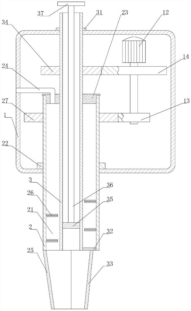
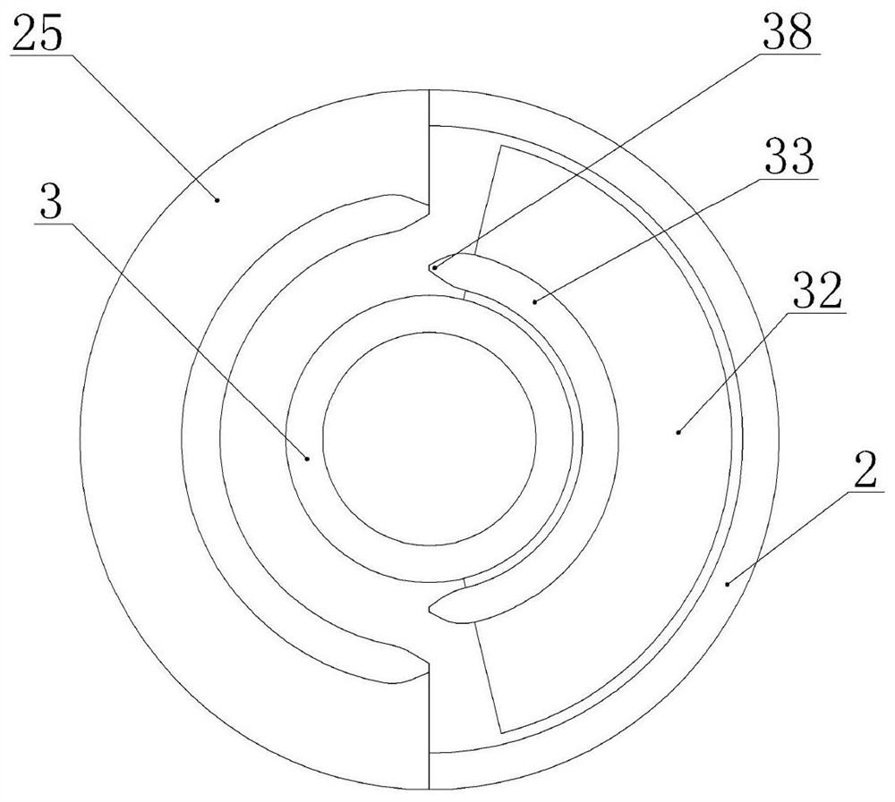
[0034] Implants for hair transplantation, such as figure 1 As shown, it includes a casing 1, a first slotting mechanism and a second slotting mechanism. The casing 1 is cylindrical, and the first slotting mechanism includes a negative pressure tube 2 and a first arc knife glued to the lower end of the negative pressure tube 2. 25. The upper end of the negative pressure tube 2 runs through the bottom of the shell 1 and fits with the shell 1. The negative pressure tube 2 can rotate relative to the shell 1. The upper end of the negative pressure tube 2 is glued with the first mounting block 22, and the lower end of the first mounting block 22 is connected to the The bottoms of the shells 1 are attached to each other to prevent the negative pressure tube 2 from slipping out from the bottom of the shells 1 . The second slotting mechanism includes a planting tube 3 and a second arc knife 33. The outer diameter of the planting tube 3 is smaller than the inner diameter of the negative...

Embodiment 2

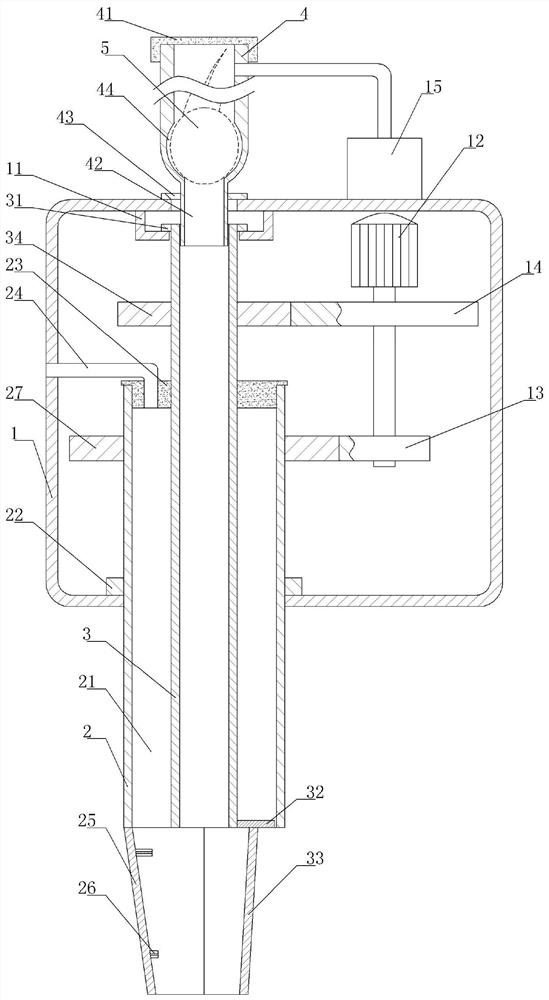
[0048] This embodiment differs from Embodiment 1 in that, as image 3 As shown, the planting tube 3 in this embodiment is not provided with a piston 35, a push rod 36 and a limit block 37, and the upper end of the planting tube 3 does not extend from the planting opening to the top of the casing 1, and the inner wall of the top of the casing 1 is welded with an L-shaped The supporting block 11, the second mounting block 31 is placed on the supporting block 11. In this embodiment, a placement tube 4 is provided above the planting tube 3, and the lower end of the placing tube 4 is provided with a guide section 42 whose outer diameter is smaller than the inner diameter of the planting tube 3. The lower end of the guide section 42 extends from the planting opening into the casing 1 and into the planting tube. 3, a ring-shaped third mounting block 43 is glued on the guide section 42, and the third mounting block 43 is located above the casing 1 and glued to the top wall of the casi...


PUM


Abstract

The invention relates to the field of hair transplantation apparatus, and particularly discloses a planter for hair transplantation. The planter comprises a housing, a first grooving mechanism and a second grooving mechanism, wherein the first grooving mechanism comprises a negative pressure pipe which is rotatably connected with the housing and a first arc-shaped knife fixed to the lower end of the negative pressure pipe; a negative pressure generator communicates with the negative pressure pipe; the second grooving mechanism comprises a planting pipe which is rotatably connected with the housing and a second arc-shaped knife fixed to the lower end of the planting pipe; the planting pipe is located in the negative pressure pipe, and the planting pipe and the negative pressure pipe are coaxial; a driving piece for driving the negative pressure pipe and the planting pipe to rotate is fixed to the inner part of the housing; a cross section of the first arc-shaped knife and a cross section of the second arc-shaped knife are arc, and a side wall of the first arc-shaped knife and a side wall of the second arc-shaped knife are cutting edge parts; and a planting opening which is aligned to the planting pipe is formed in a position, away from the side wall of the first arc-shaped knife, of the housing. Through the adoption of a scheme of the planter disclosed by the invention, blood produced by hole forming can be cleaned.

Description

technical field [0001] The invention relates to the field of hair transplantation instruments, and specifically discloses a planter for hair transplantation. Background technique [0002] Hair transplantation can transplant the hair from the back of the human body to the head and other parts without hair follicles and no hair growth, so that the transplanted hair can survive and grow naturally in the new part, so as to achieve the purpose of supplementing the number of hairs and modifying the distribution of local hairs. to achieve a beautiful effect. [0003] For hair transplantation, it is necessary to use microsurgery to remove healthy hair follicle tissue from the back of the brain, and then plant it after careful processing and cultivation. Before planting, it is necessary to open a hole in the site to be planted, and then implant the hair follicles into the hole. The current drilling and planting operations use different tools, which will cause damage to the planting...

Claims


Application Information

Patent Timeline
IPC IPC(8): A61B17/00
CPCA61B17/00A61B2017/00752
Inventor 曾沥缘王红霞
Owner THE FIRST AFFILIATED HOSPITAL OF ARMY MEDICAL UNIV
Why Eureka
Try Eureka