Gear rotating grinding device for automobile steering gear

A technology for automotive steering gears and gears, which is applied in grinding/polishing safety devices, machine tools suitable for grinding workpiece planes, grinding machines, etc., which can solve the problems of no grinding dust treatment channels, unfavorable fast grinding, long installation and fixed time, etc. problem, to achieve the effect of convenient and firm grinding, simple structure and low production cost

Active Publication Date: 2019-11-29
广东星星汽配科技有限公司
View PDF6 Cites 0 Cited by
  • Summary
  • Abstract
  • Description
  • Claims
  • Application Information

AI Technical Summary

Problems solved by technology

[0002] Automobile gears, as one of the auto parts, need to be polished on the surface after processing and forming. In the prior art, the fixing of automobile gears is more complicated, the installation and fixing time is more, and it is not conducive to the rapid grinding. At the same time, during the grinding process There is no special channel for the treatment of grinding dust, which is easy to cause physical injury to the operator, and needs to be improved urgently

Method used


Image

  • Gear rotating grinding device for automobile steering gear
  • Gear rotating grinding device for automobile steering gear
  • Gear rotating grinding device for automobile steering gear

Examples


specific Embodiment approach 1

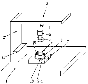
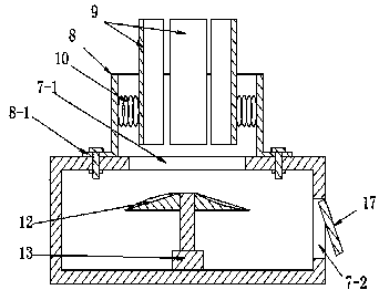
[0023] see as Figure 1-Figure 3 As shown, the technical solution adopted in this specific embodiment is: it includes a bottom plate 1, a vertical plate 2, a top plate 3, an electric lifting rod 4, a grinding motor 5, a grinding wheel 6, a dust collection box 7, a positioning piece fixing ring 8, a positioning Sheet 9, tension spring 10, electric control box 11, turbine 12, turbine rotating motor 13; one side of the bottom plate 1 is welded with a vertical plate 2, and the upper part of the vertical plate 2 is welded with a top plate 3 at the top of the bottom plate 1, and the top plate 3 The lower surface of the lower surface is connected and fixed with the electric control end of the electric lifting rod 4 by bolts, and the output shaft of the electric lifting rod 4 is welded and fixed on the electric control end shell of the grinding motor 5, and the output shaft of the grinding motor 5 is connected with a grinding wheel 6; The upper surface of the bottom plate 1 is welded ...

specific Embodiment approach 2

[0029] see Figure 4 and Figure 5The difference between this specific embodiment and the specific embodiment one is that the fixed bolt 18 is replaced by a buffer spring 16, the upper end of the buffer spring 16 is welded and fixed on the bottom surface of the fixed flange 8-1, and the buffer spring 16 is The lower ends are all welded and fixed on the spring mounting seat 15, the spring mounting seat 15 is an annular structure, and its upper edge is welded and fixed on the upper surface of the dust collection box 7, and is located below the opening 7-1. The side 8-1 is movably embedded in the opening 7-1; the symmetrical bolts on the left and right sides of the lower surface of the top plate 3 are fixed with a Y-direction slide rail 19, and a Y-direction slider 20 is movable on the Y-direction slide rail 19. An X-direction slide rail 23 is welded between the left and right Y-direction sliders 20, and an X-direction slider 24 is movable on the X-direction slide rail 23. The u...


PUM


Abstract

The invention discloses a gear rotating grinding device for an automobile steering gear and relates to the technical field of automobile part machining equipment. A dust collection box is arranged onthe upper surface of a base plate and located under a grinding wheel. The upper surface of the dust collection box is provided with an opening. The upper part of the periphery of the opening is provided with a locating plate fixing ring. The inner wall of the locating plate fixing ring is connected with a plurality of tension springs. A locating plate is connected to the outer end of each tensionspring. The upper edges of the locating plates are higher than the upper edge of the locating plate fixing ring, and the multiple locating plates form a ring structure. A gear to be ground can be ground conveniently and firmly, meanwhile, a certain grinding dust treating way is provided, dust flying in the grinding process is greatly reduced, the machining environment is improved, safety is higher, and practicability is higher.

Description

technical field [0001] The invention relates to the technical field of auto parts processing equipment, in particular to a gear rotation grinding device for an automobile steering gear. Background technique [0002] Automobile gears, as one of the auto parts, need to be polished on the surface after processing and forming. In the prior art, the fixing of automobile gears is more complicated, the installation and fixing time is more, and it is not conducive to the rapid grinding. At the same time, during the grinding process There is no dedicated grinding dust treatment channel in the machine, which is easy to cause physical injury to the operator, and needs to be improved urgently. Contents of the invention [0003] The object of the present invention is to aim at the defects and deficiencies of the prior art, to provide a simple in structure, reasonable in design, and easy to use gear rotation grinding device for automobile steering gear, which can conveniently and firmly...

Claims


Application Information

Patent Timeline
IPC IPC(8): B24B7/10B24B41/06B24B41/02B24B55/06
CPCB24B7/10B24B41/06B24B41/02B24B55/06
Inventor 孔伟杰郭建勇周伟祥李怀跃朱作全
Owner 广东星星汽配科技有限公司
Why Eureka
Try Eureka