
Pressure and flow monitoring terminal of tap water pipe network

A flow monitoring and water pipe technology, applied in pipeline systems, mechanical equipment, gas/liquid distribution and storage, etc., can solve problems such as hidden safety hazards, lack of monitoring of the surrounding environment, lack of equipment protection measures, etc. Guarantee personal and property safety, protect personal safety and the effect of pipe network facilities

Inactive Publication Date: 2019-11-29
HIGHREACH MEASURING&CONTROLLING SYST CO LTD
View PDF8 Cites 0 Cited by
  • Summary
  • Abstract
  • Description
  • Claims
  • Application Information

AI Technical Summary

Problems solved by technology

[0005] The purpose of the present invention is to provide a monitoring terminal for the pressure and flow of the tap water pipe network, so as to solve the problem in the existing tap water pipe network monitoring terminal mentioned above, most of the monitoring points are usually only equipped with pressure transmitters and flow meters Used to monitor the pipeline network, it does not have the function of monitoring the surrounding environment, especially in the pressurization station and dispatching station, lack of necessary equipment protection measures, and there are problems and deficiencies of potential safety hazards

Method used


Image

  • Pressure and flow monitoring terminal of tap water pipe network
  • Pressure and flow monitoring terminal of tap water pipe network

Examples


Embodiment approach

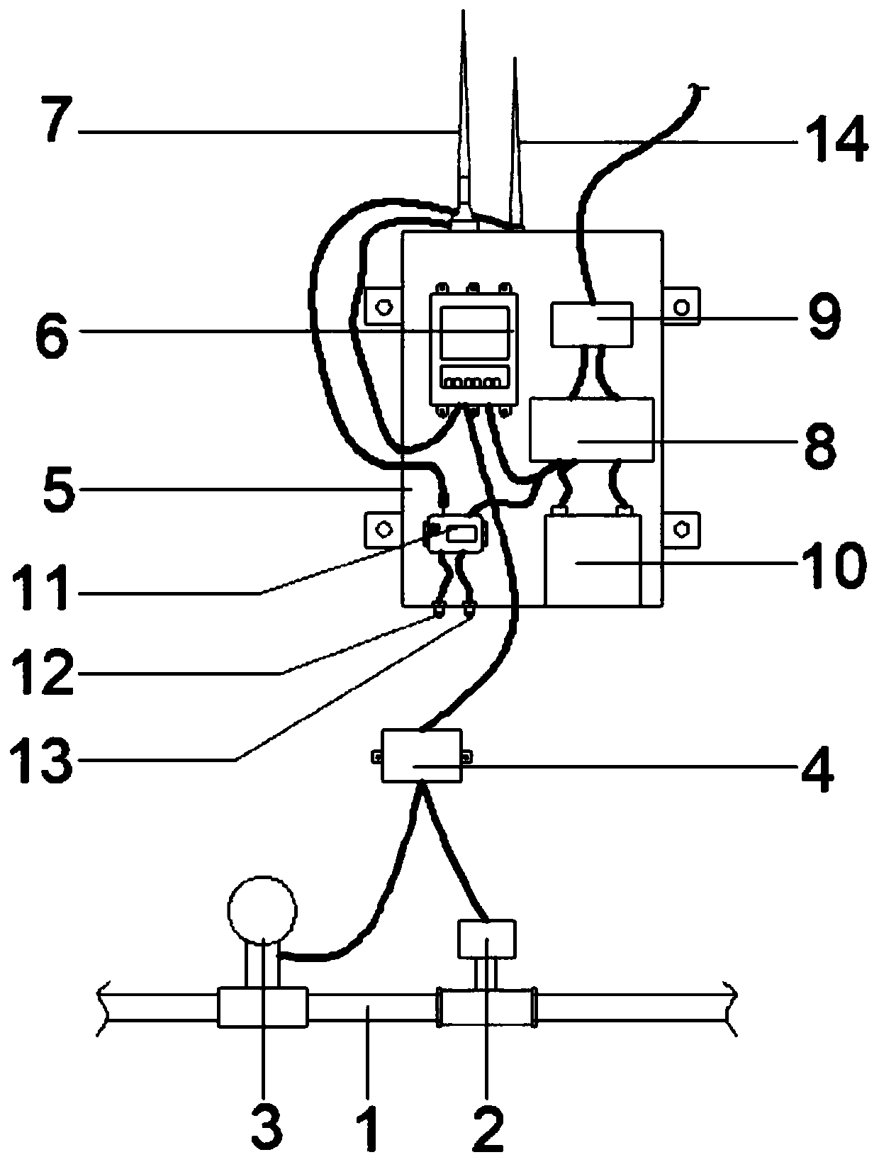
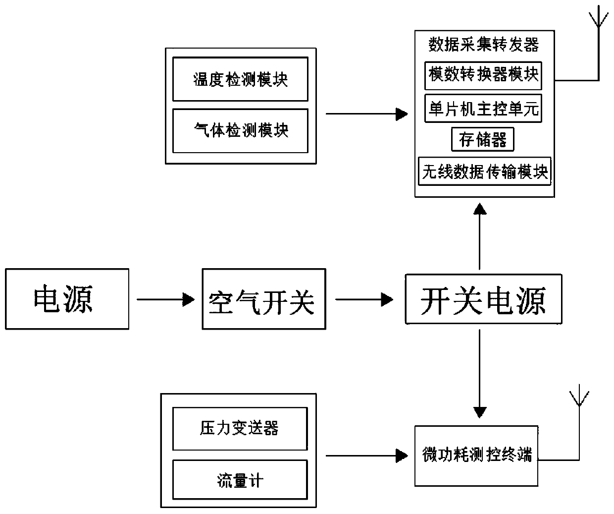
[0024] A pressure and flow monitoring terminal of a tap water pipe network, comprising: a pipeline 1, a flow meter 2, a pressure transmitter 3, a waterproof junction box 4, a protective box 5, a micro-power consumption measurement and control terminal 6, a first antenna 7, a switching power supply 8, Air switch 9, battery 10, data acquisition transponder 11, temperature sensor 12, gas sensor 13, second antenna 14; the middle part of pipeline 1 is provided with flowmeter 2, and pipeline 1 and flowmeter 2 are connected through flange; The transmitter 3 is set in the middle of the pipeline 1, and the pressure transmitter 3 is connected in series with the pipeline 1; the waterproof junction box 4 is set on one side of the pressure transmitter 3, and the waterproof junction box 4 and the pressure transmitter 3 pass through The wires are connected; the protective box 5 is arranged on one side of the waterproof junction box 4; the micro-power consumption measurement and control termin...


PUM


Abstract

The invention provides a pressure and flow monitoring terminal of a tap water pipe network. The monitoring terminal comprises a flowmeter, a pressure transmitter, a temperature sensor and a gas sensor, wherein the flowmeter is arranged in the middle part of a pipeline, and the pipeline is connected with the flowmeter through a flange; the pressure transmitter is arranged in the middle part of thepipeline, and the pressure transmitter is connected with the pipeline in series; a micro-power consumption measurement and control terminal is arranged inside a protection box, and the micro-power consumption measurement and control terminal is fixedly connected with the protection box through bolts; the temperature sensor is arranged at the bottom of the protection box, and the temperature sensoris connected with a data acquisition transponder through wires; and a gas sensor is arranged at the bottom of the protection box, and the gas sensor is connected with the data acquisition transponderthrough wires. The pressure and flow monitoring terminal of the tap water pipe network is improved, so that the device has the advantages that environmental conditions around the pipe network can bemonitored, potential safety hazards are effectively eliminated, personal safety and pipe network facilities are protected, and therefore the problems and defects of an existing device are effectivelysolved.

Description

technical field [0001] The present invention relates to the technical field of tap water pipe network monitoring terminals, and more specifically, to a tap water pipe network pressure flow rate monitoring system capable of real-time monitoring of the surrounding environment of the pipe network, effectively eliminating potential safety hazards, and protecting personal safety and pipe network facilities. Monitoring terminal. Background technique [0002] In the tap water pipe network system, in order to ensure the normal operation of the tap water pipe network, there are usually several devices used to monitor the pipe network, such as pressure transmitters, flow meters, water quality monitors and other devices, among which pressure transmitters and Flow meters are widely used monitoring devices. [0003] In the existing water pipe network monitoring terminals, most of the monitoring points are usually only equipped with pressure transmitters and flow meters for monitoring th...

Claims


Application Information

Patent Timeline
Patent Type & Authority Applications(China)
IPC IPC(8): F17D5/00F17D3/18
CPCF17D3/18F17D5/00
Inventor 杨丰杨建军贺桂玲杨益民
Owner HIGHREACH MEASURING&CONTROLLING SYST CO LTD
Learn More