Design method for precision electrolytic machining cathode position consistency

A design method and consistent technology, applied in the direction of measuring devices, mechanical devices, mechanical measuring devices, etc., can solve the problem of waste products produced by processing parts, the lack of consideration of the consistency of the cathode installation space, and the three-dimensional space cathode position hinders precision electrolytic processing technology Engineering application and other issues, to achieve the effect of high precision and simple operation

Inactive Publication Date: 2019-11-29
AECC AVIATION POWER CO LTD
View PDF9 Cites 0 Cited by
  • Summary
  • Abstract
  • Description
  • Claims
  • Application Information

AI Technical Summary

Problems solved by technology

[0002] The blisk is one of the core components of the fourth-generation and above-generation aero-engines. Because it adopts the structural design of the integrated disc hub and blade, it eliminates the gap between the tenon and tenon in the traditional blade and disc structure. The loss caused by the escape flow in the groove improves the working efficiency of the aeroengine and further increases the propulsion ratio of the engine. At present, the manufacturing process of the blisk is mainly based on milling and electrolytic machining, and with the application of numerical control technology to electrolytic machining Since then, precision electrolytic machining has increasingly become the mainstream processing technology at home and abroad. Precision electrolytic machining has many advantages such as no loss of tools, good surface quality, high processing e...

Method used


Image

  • Design method for precision electrolytic machining cathode position consistency
  • Design method for precision electrolytic machining cathode position consistency
  • Design method for precision electrolytic machining cathode position consistency

Examples


Embodiment Construction

[0037] The present invention will be further described in detail below in conjunction with specific embodiments, which are explanations of the present invention rather than limitations.

[0038] When using the precision electrolysis processing method to process the overall blisk blade of the aeroengine, the detailed steps of the three-dimensional spatial position consistency determination method for the repeated installation of the cathode of the tool are as follows:

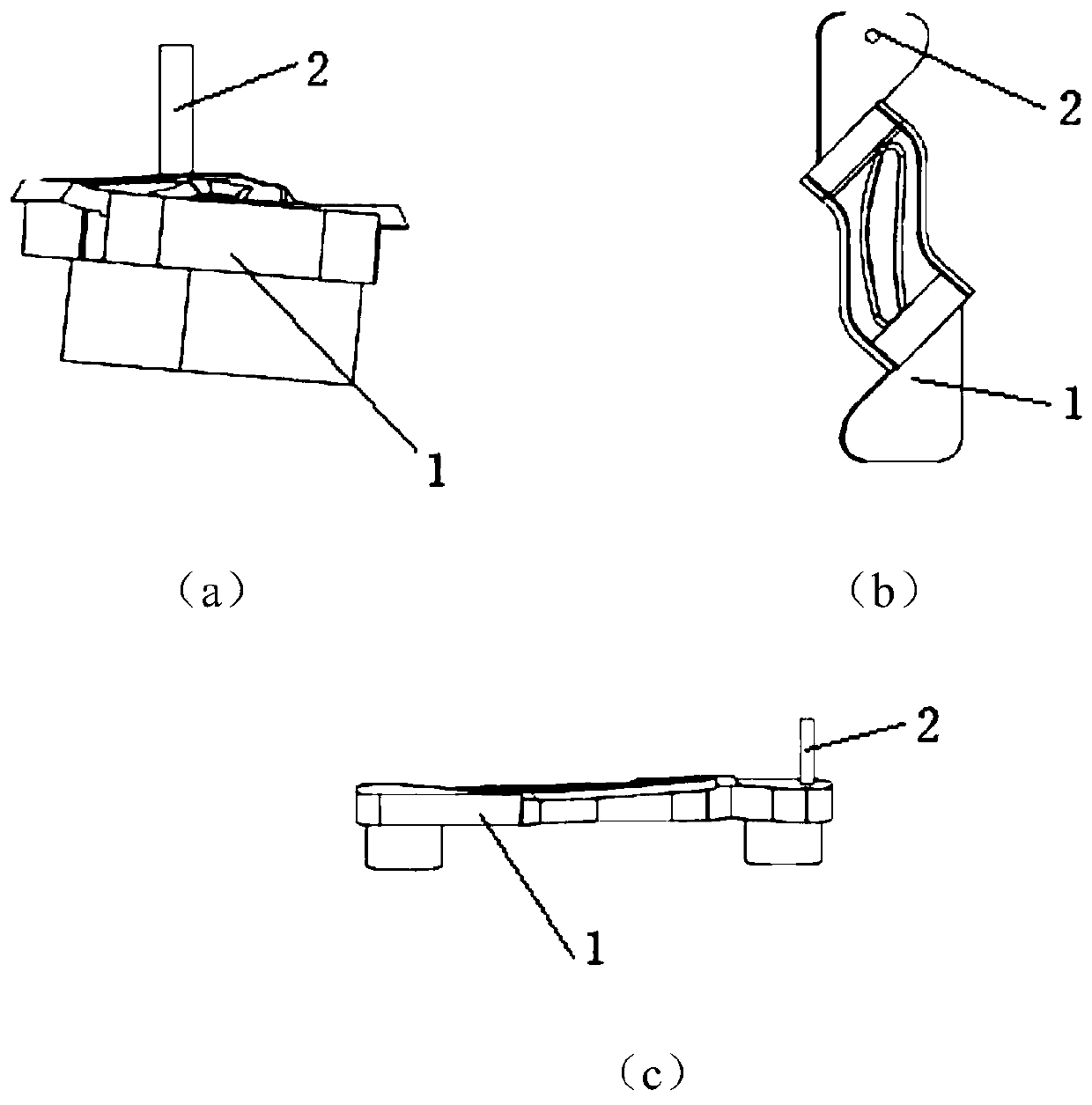
[0039] 1) Design positioning pin 2:

[0040] On the tool cathode 1, it is necessary to design a positioning pin 2 with a three-dimensional space position for tool setting. The positioning pin 2 requires high machining accuracy. Tool setting operation; the diameter of the positioning pin Φ is 6mm, and the length of the positioning pin protruding from the surface of the cathode is 16mm;

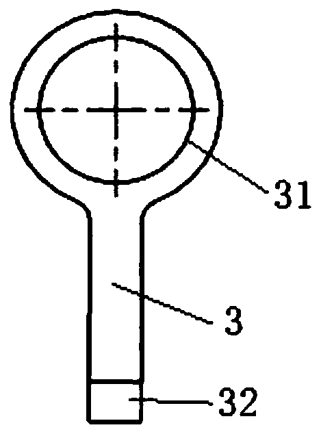
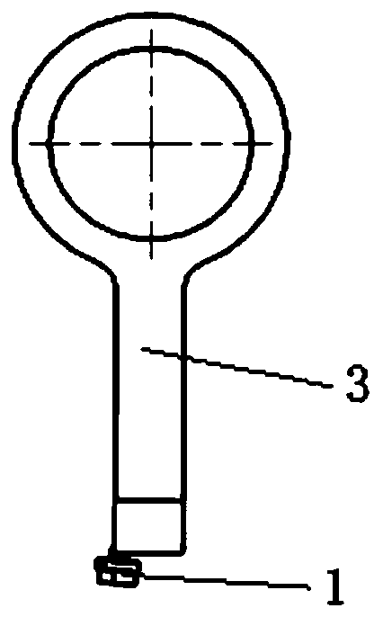
[0041] 2) Design cathode standard block device 3:

[0042] Cathode standard block device 3 should be able to be fixedly insta...


PUM


Abstract

The invention discloses a design method for precision electrolytic machining cathode position consistency. A positioning pin is additionally arranged on a traditional tool cathode, a cathode standardblock device is additionally arranged on electrolysis equipment, the tool cathode with the positioning pin and the cathode standard block device are subjected to tool setting operation so as to recordstandard coordinate values of the X axis, the Y axis and the Z axis of the electrolysis equipment; when the tool cathode is reinstalled later on, the standard values are used as a judgment reference,the new tool setting values of the X axis, the Y axis and the Z axis are respectively compared with the standard coordinate values, if the difference value of the three values is smaller than 0.05, the position consistency of the tool cathode is considered to be good, and otherwise, the tool cathode needs to be reinstalled until the requirements are met. According to the method, the consistency of the three-dimensional space installation position on the electrolysis equipment can be controlled before the tool cathode is subjected to part machining, so that the inconsistency of installation ofthe tool cathode due to the influence of any factors on the tool cathode and the equipment joint part is avoided.

Description

technical field [0001] The invention belongs to the technical field of precision electrolytic machining, and in particular relates to a method for designing the position consistency of cathodes in precision electrolytic machining. Background technique [0002] The blisk is one of the core components of the fourth-generation and above-generation aero-engines. Because it adopts the structural design of the integrated disc hub and blade, it eliminates the gap between the tenon and tenon in the traditional blade and disc structure. The loss caused by the escape flow in the groove improves the working efficiency of the aeroengine and further increases the propulsion ratio of the engine. At present, the manufacturing process of the blisk is mainly based on milling and electrolytic machining, and with the application of numerical control technology to electrolytic machining Since then, precision electrolytic machining has increasingly become the mainstream processing technology at ...

Claims


Application Information

Patent Timeline
IPC IPC(8): G01B5/004G01B5/00
CPCG01B5/003G01B5/004
Inventor 陈文亮王福平吴晓锋雷晓晶胡思嘉李元任景刚黄楚芃
Owner AECC AVIATION POWER CO LTD
Why Eureka
Try Eureka