
Optical fiber torsion testing device and method

A testing device and twisting technology, applied in measuring devices, using optical devices, angle/taper measurement, etc., can solve problems such as low efficiency, achieve accurate test results, reduce labor costs, and be easy to operate

Pending Publication Date: 2019-11-29
ZHONGTIAN TECH FIBER OPTICS +2
View PDF1 Cites 0 Cited by
  • Summary
  • Abstract
  • Description
  • Claims
  • Application Information

AI Technical Summary

Problems solved by technology

[0005] Patent CN107238342A proposes a measuring device for optical fiber torsion. From its description, it can be seen that the length of optical fiber that can be tested by this measuring device is relatively short, and the method of manually counting the number of turns of the twisting angle is still used, and the efficiency is low.

Method used


Image

  • Optical fiber torsion testing device and method
  • Optical fiber torsion testing device and method
  • Optical fiber torsion testing device and method

Examples


Embodiment Construction

[0039] In order to make the purpose, technical solutions and advantages of the present invention clearer, the technical solutions in the embodiments of the present invention will be clearly and completely described below in conjunction with the accompanying drawings in the embodiments of the present invention. Obviously, the described embodiments are only Some, but not all, embodiments of the invention. Based on the embodiments of the present invention, all other embodiments obtained by persons of ordinary skill in the art without making creative efforts belong to the protection scope of the present invention.

[0040] It should be noted that the descriptions of the present invention on directions such as "left end" and "right end" are all defined based on the orientation or position relationship shown in the drawings, and are only for the convenience of describing the present invention and simplifying the description, rather than indicating Or imply that the device described ...


PUM


Abstract

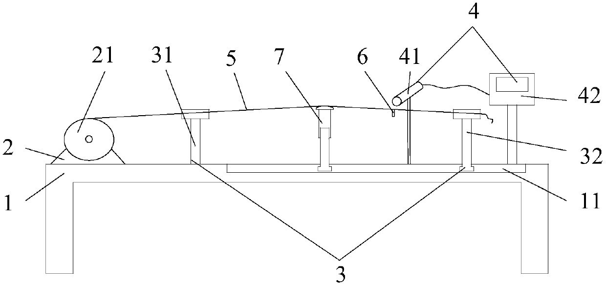
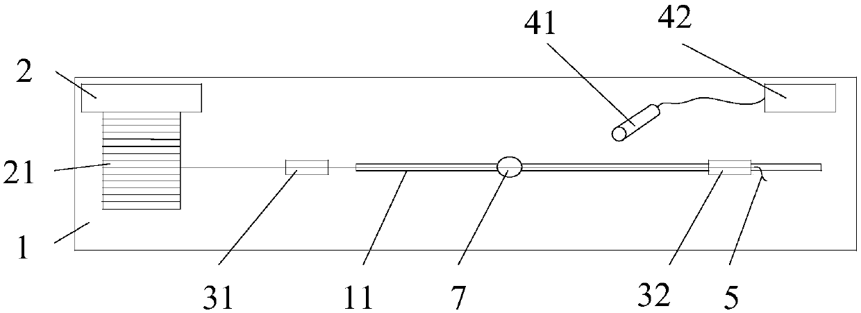
The invention discloses an optical fiber torsion testing device and method and belongs to the technical field of optical fiber testing. The device comprises a test platform, a fiber releasing bracket,an optical fiber clamping piece and a driving motor. A slide rail is arranged at the horizontal position of the test platform. The optical fiber clamping piece is arranged on the slide rail in a sliding manner. The test platform, the fiber placing support, the slide rail and the optical fiber clamping piece are connected with the driving motor. The optical fiber torsion testing device is characterized in that the device also comprises a photoelectric detection device; the photoelectric detection device is used for detecting and recording the number of the times of the presence of an identification piece arranged on a to-be-tested optical fiber so as to obtain the optical fiber torsion of the to-be-tested optical fiber. According to the optical fiber torsion testing device and method of the invention, most of test operations can be automatically controlled by one person through the driving motor; operation is simple and convenient; labor cost is reduced; and test results are relativelyaccurate. The optical fiber torsion testing device and method can be widely applied to the field of optical fiber torsion test.

Description

technical field [0001] The invention relates to the technical field of optical fiber testing, in particular to an optical fiber twist testing device and method. Background technique [0002] The dispersion and attenuation of optical fiber are the main factors that limit the distance of optical communication. The dispersion of single-mode fiber includes chromatic dispersion and polarization mode dispersion (PMD). With the development of optical amplification technology and dispersion compensation technology, the attenuation and color The influence of degree dispersion on the optical communication network has been minimized, and PMD has a large randomness and cannot be optimized in the optical communication network, so it can only be controlled from the process of optical fiber production and cabling. [0003] The main cause of polarization mode dispersion is due to the uneven distribution of stress inside the optical fiber. In order to improve the polarization mode dispersion...

Claims


Application Information

Patent Timeline
Patent Type & Authority Applications(China)
IPC IPC(8): G01B11/26
CPCG01B11/26G01B5/24
Inventor 柴雪峰杨郭杰耿培恒曹珊珊刘志忠王震徐海涛
Owner ZHONGTIAN TECH FIBER OPTICS
Learn More