

Backlight module and display device
A backlight module and display panel technology, applied in optics, nonlinear optics, instruments, etc., can solve problems such as inability to provide light sources and affect the display effect of full-screen display devices, so as to improve display effects, improve user experience, and improve Effect of Backlight Brightness
- Summary
- Abstract
- Description
- Claims
- Application Information
AI Technical Summary
Problems solved by technology
Method used
Image

Examples
Embodiment 1
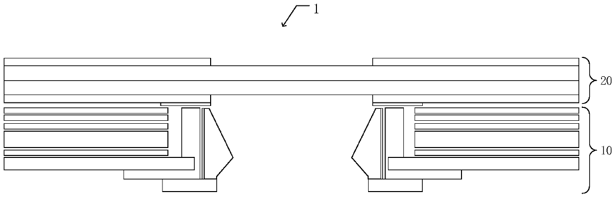
[0051] An embodiment of the present invention provides a display device 1, such as figure 1 As shown, the display device 1 includes a backlight module 10 and a display panel 20 . The display device 1 has a full-screen display effect, and it can be any product or component with a display function such as a mobile phone, a tablet computer, or a notebook computer. Wherein, the display panel 20 is disposed on the backlight module 10 .
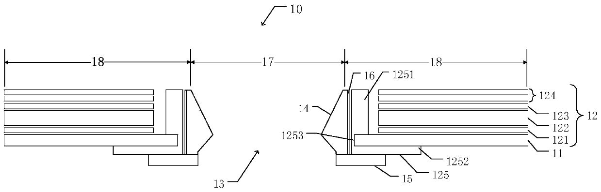
[0052]Such as figure 2 As shown, the backlight module 10 has a light-transmitting area 17 and a non-light-transmitting area 18 , and the non-light-transmitting area 18 surrounds the light-transmitting area 17 . The light-transmitting area 17 is used to provide a light-taking channel for the camera, and the non-light-transmitting area 18 is used for normal image display.
[0053] The backlight module 10 includes a substrate 11 , an optical film structure layer 12 , a through hole 13 and a light control structure. The optical film structure laye...
Embodiment 2
[0069] An embodiment of the present invention provides a display device 1, such as Figure 5 As shown, the display device 1 includes a backlight module 10 and a display panel 20 . The display device 1 has a full-screen display effect, and it can be any product or component with a display function such as a mobile phone, a tablet computer, or a notebook computer. Wherein, the display panel 20 is disposed on the backlight module 10 .
[0070] Such as Image 6 As shown, the backlight module 10 has a light-transmitting area 17 and a non-light-transmitting area 18 , and the non-light-transmitting area 18 surrounds the light-transmitting area 17 . The light-transmitting area 17 is used to provide a light-taking channel for the camera, and the non-light-transmitting area 18 is used for normal image display.
[0071] The backlight module 10 includes a substrate 11 , an optical film structure layer 12 , a through hole 13 and a light control structure. The optical film structure lay...
Embodiment 3
[0086] An embodiment of the present invention provides a display device 1, such as Figure 5 As shown, the display device 1 includes a backlight module 10 and a display panel 20 . The display device 1 has a full-screen display effect, and it can be any product or component with a display function such as a mobile phone, a tablet computer, or a notebook computer. Wherein, the display panel 20 is disposed on the backlight module 10 .
[0087] Such as Image 6 As shown, the backlight module 10 has a light-transmitting area 17 and a non-light-transmitting area 18 , and the non-light-transmitting area 18 surrounds the light-transmitting area 17 . The light-transmitting area 17 is used to provide a light-taking channel for the camera, and the non-light-transmitting area 18 is used for normal image display.
[0088] The backlight module 10 includes a substrate 11 , an optical film structure layer 12 , a through hole 13 and a light control structure. The optical film structure lay...
PUM
| Property | Measurement | Unit |
|---|---|---|
| Thickness | aaaaa | aaaaa |
Abstract
Description
Claims
Application Information