
Self-rotating detachable easy-to-clean filter element

A detachable and self-rotating technology, which is applied in the field of air purification, can solve the problems of inconvenient cleaning of the filter body, achieve the effect of reducing cleaning dead angle, good capture, and improving cleaning effect

Inactive Publication Date: 2019-12-03
新昌县大菠萝农业发展有限公司
View PDF7 Cites 4 Cited by
  • Summary
  • Abstract
  • Description
  • Claims
  • Application Information

AI Technical Summary

Problems solved by technology

[0005] The purpose of the present invention is to solve the problem of inconvenient cleaning of the existing filter element body, and provide a self-rotating detachable easy-to-clean filter element with simple operation and good cleaning effect

Method used


Image

  • Self-rotating detachable easy-to-clean filter element
  • Self-rotating detachable easy-to-clean filter element
  • Self-rotating detachable easy-to-clean filter element

Examples


Embodiment 1

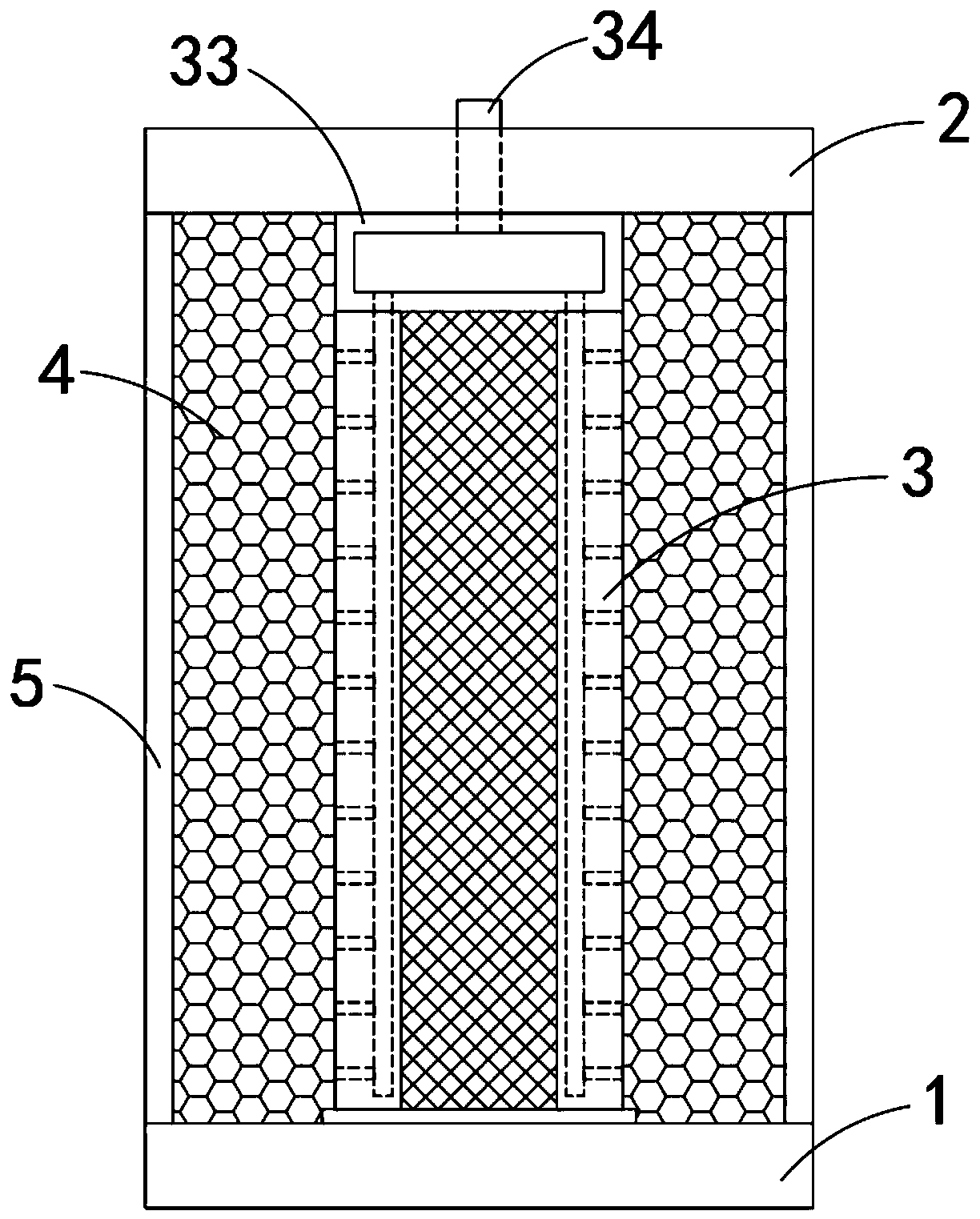
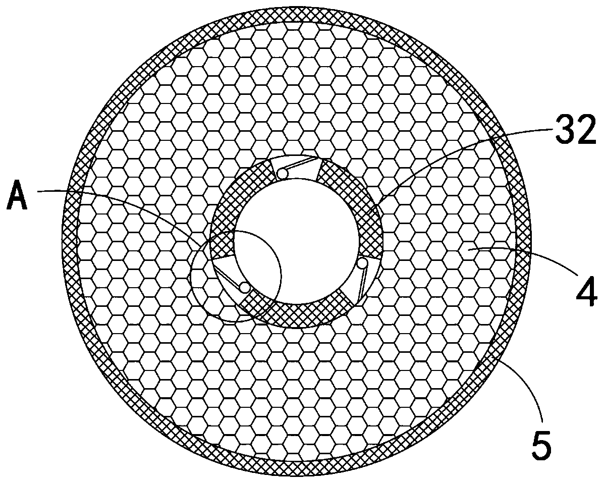
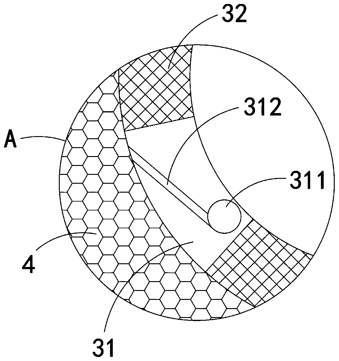
[0021] Such as Figure 1-3 As shown, a self-rotating detachable easy-to-clean filter element includes a base 1, a top seat 2, an inner cylinder 3, a filter element body 4 and an outer cylinder 5, the inner cylinder 3 can rotate freely along its axial direction, and the filter element body 4 is connected to the outer cylinder. The inner side wall of the tube 5 is fixedly connected, and the inner tube 3 includes a plurality of fixing bars 31 and filter screen plates 32 fixed between the fixing bars 31. The fixing bars 31 and the filter screen plates 32 are arc-shaped strips with the same radian. The fixed strip 31 and a plurality of filter screen plates 32 are fixedly connected together at intervals in turn to form an inner cylinder 3, the upper end of the inner cylinder 3 is fixedly connected with a rotating cylinder 33, and the rotating cylinder 33 is airtightly arranged for conducting airflow, and the upper end of the rotating cylinder 33 is fixed Connected with the air intak...

Embodiment 2

[0025] Such as Figure 4-5 As shown, the difference between the present embodiment and the first embodiment is that: the lower end of the inner cylinder 3 is fixedly connected with a friction ring 35 , and static electricity will be generated when friction occurs between the friction ring 35 and the base 1 .

[0026] In this embodiment, when the friction ring 35 rotates with the inner cylinder 3, it will rub against the base 1 and generate static electricity. Under the action of static electricity, it will absorb the blown dust particles, thereby preventing the dust from escaping everywhere. , causing secondary pollution to the surrounding environment.

[0027] Further, the outer cylinder 5 is provided with a plurality of strip-shaped slots with upward openings. Conductive strips 51 are arranged in the strip-shaped slots. The lower ends of each conductive strip 51 are connected to the base 1 in rotation. The curvature of the barrel 5 is consistent, and a plurality of discharg...


PUM


Abstract

The invention belongs to the technical field of air purification, and particularly relates to a self-rotating detachable easy-to-clean filter element. The filter element includes a base seat, a top seat, an inner cylinder, a filter element body and an outer cylinder; the inner cylinder can rotate freely along the axial direction, and the inner cylinder includes a plurality of fixing bars and filter net plates fixed among the fixing bars; the upper end of the inner cylinder is fixedly connected with a rotating cylinder, and the upper end of the rotating cylinder is fixedly connected with a gasinlet pipe that penetrates the top seat and is rotatably connected with the top seat; and one vertically-arranged gas outlet channel communicating with the rotating cylinder is arranged in each fixing bar, a plurality of horizontally-arranged gas discharging micropores are arranged in the side wall of each gas outlet channel, and the axes of the gas discharging micropores are rotationally symmetrically distributed with the axis of the inner cylinder. According to the filter element provided by the invention, the gas outlet channels and the gas discharging micropores are arranged, when high-speed flowing gas blows dust from the inside to outside, the counter-acting force generated by the gas discharging micropores drives the inner cylinder to rotate, so that the interior of the filter element body can be comprehensively cleaned, and the cleaning effect of the filter element body can be further improved.

Description

technical field [0001] The invention belongs to the technical field of air purification, and in particular relates to a self-rotating detachable easy-cleaning filter element. Background technique [0002] An air purifier is a common household appliance used to purify indoor air; its main working part is the filter body, which separates air and particulate impurities through its internal filter pores. [0003] When cleaning the existing filter element body, most of them use high-speed airflow to clean it with a high-pressure air gun. However, due to the deep depth of the filter element body and the inconvenient fixing, the staff can only clean it from the outside, so that the high-speed airflow used for cleaning is different from the When the filter body is working, the direction of the filtered air flow is opposite, so it is difficult to achieve a good cleaning effect; in addition, due to the deep internal depth of the filter body, it is prone to incomplete cleaning, and the...

Claims


Application Information

Patent Timeline
Patent Type & Authority Applications(China)
IPC IPC(8): B01D46/00B01D46/24
CPCB01D46/0032B01D46/24B01D46/66
Inventor 赵婷婷
Owner 新昌县大菠萝农业发展有限公司
Learn More