A rapid prototyping extruder for pit tube

An extruder and dimple technology, which is applied in the field of dimple tube rapid prototyping extrusion machines, can solve the problems of complex adjustment operation of dimple spacing parameters, inconvenient dimple spacing adjustment, low production efficiency, etc., to improve the dimple tube Production speed, reduce the production cost of dimpled pipe, and improve the effect of processing and production speed

Active Publication Date: 2020-08-18
成都市成航发科技有限公司
View PDF10 Cites 0 Cited by
  • Summary
  • Abstract
  • Description
  • Claims
  • Application Information

AI Technical Summary

Problems solved by technology

However, although there are many kinds of heat transfer tube processing and manufacturing devices, there are currently few extrusion molding devices suitable for dimpled heat transfer tubes.
[0005] However, in recent years, some dimpled pipe manufacturing devices have been disclosed in China, such as: Patent No. "CN2017106146693" discloses a stamping-type industrial high-efficiency pipe forming table. Two rows of dimples, no multiple dimples can be formed on the same section
Patent No. "CN2017106146640" discloses a multi-cylinder type dimple heat transfer tube extrusion molding device. When the device adjusts the dimple spacing, it needs to disassemble the device and then replace the extrusion plate, so the dimple spacing parameter adjustment operation is complicated
Patent No. "CN201710614666X" discloses a staggered trachea heat transfer tube extrusion molding device, which can only form 6 pits (that is, one pitch) at a time, so the production efficiency is low and the production cost is high
Patent No. "CN2017106146585" discloses a wedge-type dimpled heat transfer tube extrusion molding device, which also has the problem of inconvenient adjustment of dimple spacing

Method used


Image

  • A rapid prototyping extruder for pit tube
  • A rapid prototyping extruder for pit tube
  • A rapid prototyping extruder for pit tube

Examples


Embodiment Construction

[0035] The present invention will be described in further detail below in conjunction with the accompanying drawings.

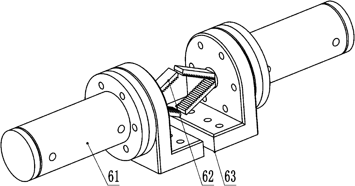
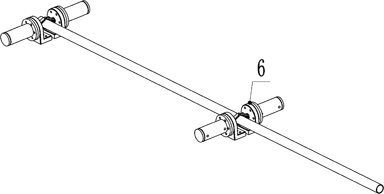
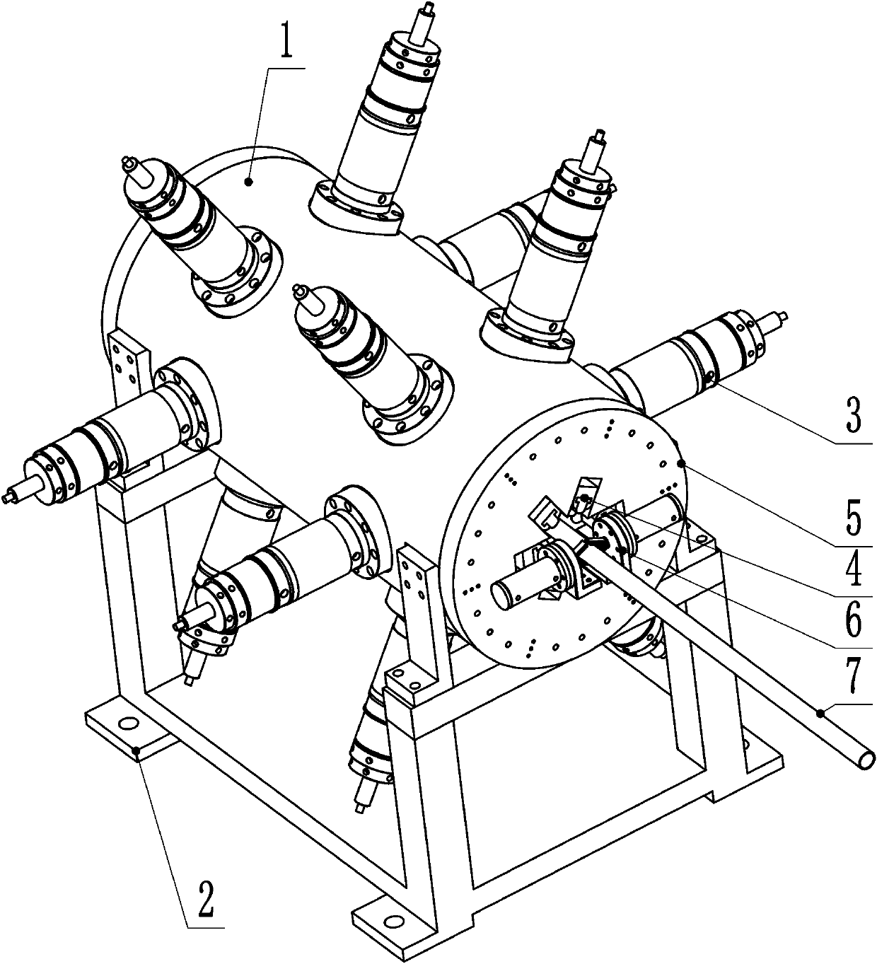
[0036] refer to Figure 1 ~ Figure 2 , a pit tube rapid prototyping extrusion machine is composed of a power system 3, a support system 1, a frame system 2, an extrusion system 4, a guide system 5, and a clamping system 6. The assembly relationship is as follows: the middle part of the top of the rack system 2 is fastened with the support system 1 through bolts, the outer surface of the support system 1 is connected with the power system 3 through bolts, and the power system 3 is connected with the extrusion system 4 through the pin shaft. The left and right ends of the pressing system 4 are respectively designed with a clamping system 6, and the jaws 62 of the clamping system 6 are in contact with pit pipes; the left and right ends of the support system 1 are respectively bolted and connected with a guide system 5. The working principle is as follows: 1. Be...


PUM


Abstract

The invention relates to a rapid forming and extruding machine for a pit tube. The rapid forming and extruding machine is composed of a supporting system, a rack system, a power system, an extrusion system, the guide systems and clamping systems. The middle of the top end of the rack system is fixedly connected with the supporting system through bolts, the supporting system is fixedly connected with the power system through bolts, and the power system is connected with the extrusion system through a pin shaft. The left and right end faces of the extrusion system are respectively provided withthe clamping systems, and the left and right end faces of the supporting system are fixedly connected with the guide systems respectively via the bolts. During work, the power system provides drivingforce for the extrusion system, the extrusion system moves along the radial direction under the guiding effects of the guiding systems, so that the pressing heads extrude the light tubes to form the concave pit tubes. Compared with the prior art, an extrusion plate adopts the T-shaped groove principle, and the extrusion parameters can be adjusted without detaching other assemblies when the pressure head is replaced or the extrusion distance is adjusted. Multiple groups of pressure heads are adopted to simultaneously extrude the light tubes, so that the pit heat transfer tube is low in production cost and high in processing and manufacturing efficiency.

Description

technical field [0001] The invention relates to the field of processing and forming of heat transfer tubes, in particular to a rapid forming extrusion machine for dimpled tubes. Background technique [0002] Heat transfer is a very common natural phenomenon and a common process in industries such as power, nuclear energy, electronics, transportation, refrigeration, chemical, petroleum, aerospace, etc. The heat exchanger occupies a key position in the above-mentioned industries. The heat exchanger is not only an indispensable part to ensure the normal operation of the entire engineering equipment, but also occupies an important share in the entire project in terms of metal consumption, power consumption and capital investment. . Taking a power plant as an example, if the boiler is also used as heat exchange equipment, the capital investment of the heat exchanger accounts for about 70% of the total investment of the power plant; in petrochemical industry, the investment of th...

Claims


Application Information

Patent Timeline
Patent Type & Authority Patents(China)
IPC IPC(8): B21C23/21
CPCB21C23/211B21C23/212B21C23/214B21C23/215B21C23/217
Inventor 谢帅董超群任连城郭正伟龚银春
Owner 成都市成航发科技有限公司
Why Eureka
Try Eureka