Automobile structural part stamping die and quick positioning tool for die

A technology for automobile structure and stamping dies, which is applied in the directions of forming tools, manufacturing tools, metal processing equipment, etc., can solve problems such as irregular structure, and achieve the effect of improving functional structure and functional structure.

Active Publication Date: 2019-12-03
徐海东
View PDF10 Cites 1 Cited by
  • Summary
  • Abstract
  • Description
  • Claims
  • Application Information

AI Technical Summary

Problems solved by technology

[0005] In order to solve the above-mentioned technical problems, the present invention provides stamping dies for automobile structural parts and quick positioning tooling for the dies, so as to solve the problems of existing stamping dies for automobiles. During application, it is necessary to use the self-made pressing plates on the stamping equipment to fix the upper and lower templates of the dies on the punching machine. On the equipment, the self-made pressure plate has an irregular structure, and the second is that the self-made pressure plate is screwed with the bolt and the pressure plate with threaded holes, and then clamped to the T-shaped card of the stamping equipment workbench and the stamping head. In the groove, press the upper mold and the lower mold on the workbench and stamping head of the stamping equipment respectively, and these self-made pressure plates must be frequently disassembled and assembled when the mold is removed and replaced, which is very troublesome.

Method used


Image

  • Automobile structural part stamping die and quick positioning tool for die
  • Automobile structural part stamping die and quick positioning tool for die
  • Automobile structural part stamping die and quick positioning tool for die

Examples


Embodiment

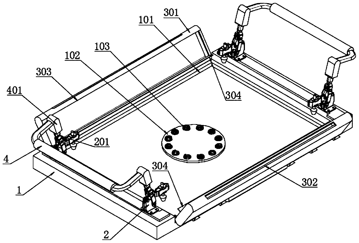
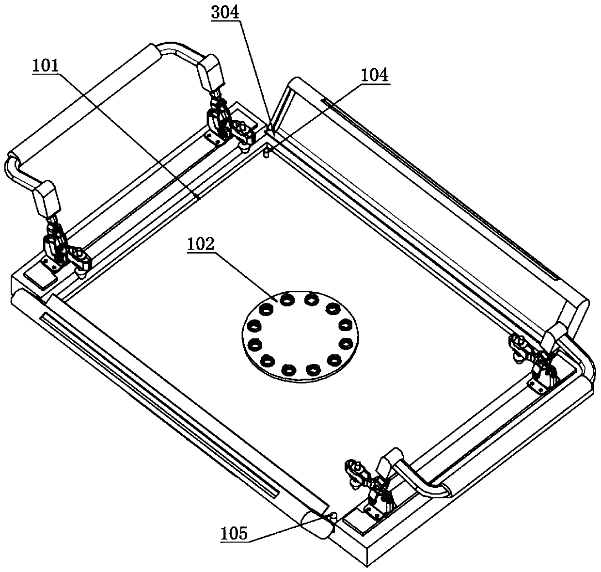
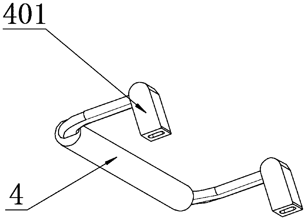
[0031] as attached figure 1 to attach Figure 11 Shown: ( Figure 1 to Figure 9 For this structure diagram, Figure 10 and Figure 11 It is the schematic diagram of template and punch equipment workbench installation mode under the prior art that this design is convenient for comparison explanation).

[0032]The present invention provides stamping molds for automotive structural parts and quick positioning tooling for molds, including a mold base 1, an inner panel 101, a middle panel 102, a compression spring 103, a first guide column 104, a second guide column 105, and a clamp 2. Fixture handle 201, swivel seat 3, stop seat 301, discharge port 302, guide groove 303, overboard 304, connecting pressure handle 4, buckle sleeve 401, mold body 5, lower template 501, bottom groove 502, bottom pad 503, the front flow plate 504, the rear flow plate 505 and the guide hole 506; the mold base 1 is a rectangular mold base, which is provided with a rectangular sinker, and a circle of ...


PUM


Abstract

The invention provides an automobile structural part stamping die and a quick positioning tool for the die. The automobile structural part stamping die comprises a rear flow plate and guide holes. Themold frame is a rectangular mold base, a rectangular sinking groove is formed in the mold base, and a circle of rectangular frame type inner panel is arranged on the inner wall of the sinking groovein a spot welding mode; four corners of the top surface of the mold frame are respectively provided with standard-part-type hand-pressing clamps, and the rubber pressing heads are all located within the inner edge range of the inner panel by a certain distance. The die body is a stamping die for a certain stamping part of an automobile; only the upper die plate of the die needs to be mounted by adopting a self-made pressing plate; the lower die plate can be pressed left and right at a time; the time for half of the upper die is saved, the die frame has the functional characteristics of blocking materials and collecting waste materials, so that the functional structure is greatly improved, and when the lower die of the die is replaced, the elastic jacking mechanism is arranged in the middleof the bottom of the opposite placing cavity of the mold frame, so that the lower die can be quickly jacked out upwards, the lower die is assisted in lifting, and the functional structure is improvedagain.

Description

technical field [0001] The invention belongs to the field of automobile mold mounting structure and mold structure technology, and more specifically relates to stamping molds for automobile structural parts and rapid positioning tooling for molds. Background technique [0002] When people talk about a car, the first thing that comes to mind is the body of the car. That is to say, the body is the iconic assembly of the car. The body represents the image characteristics of that car. In a narrow sense, automobile molds are the general term for the molds that stamp all the stamping parts on the automobile body. That is, "automobile body stamping die". For example, the top cover flanging die, the beam reinforcement plate pressing die, and some small stamping parts that constitute the structure of these stamping parts. [0003] The existing automobile stamping die needs to use the self-made pressing plate on the stamping equipment to fix the upper and lower templates of the mo...

Claims


Application Information

Patent Timeline
Patent Type & Authority Applications(China)
IPC IPC(8): B21D37/14B21D37/10
CPCB21D37/10B21D37/14
Inventor 徐海东
Owner 徐海东
Why Eureka
Try Eureka